
Fluid filter installation tool

Active Publication Date: 2014-10-23
EATON INTELLIGENT POWER LIMITED
View PDF3 Cites 0 Cited by
  • Summary
  • Abstract
  • Description
  • Claims
  • Application Information

AI Technical Summary

Benefits of technology

The invention relates to a tool for installing hydraulic fluid filters. The tool has features to reduce the risk of foreign materials getting into the fluid and to make the installation process easier. It consists of two parts that rotate relative to each other to push the filter components into the socket without needing to rotate them. This helps to keep the filter clean and reduces the effort required to install it.

Problems solved by technology

If undesired foreign object debris and other contaminants are in the fluid, moving components in contact with the fluid may wear faster than usual, or may fail entirely.
Because filters, like all components, may face mechanical issues, different parts of a filter may need to be replaced periodically.
Known filter installation tools and processes may not adequately address these needs.

Method used


Image

  • Fluid filter installation tool
  • Fluid filter installation tool
  • Fluid filter installation tool

Examples


first embodiment

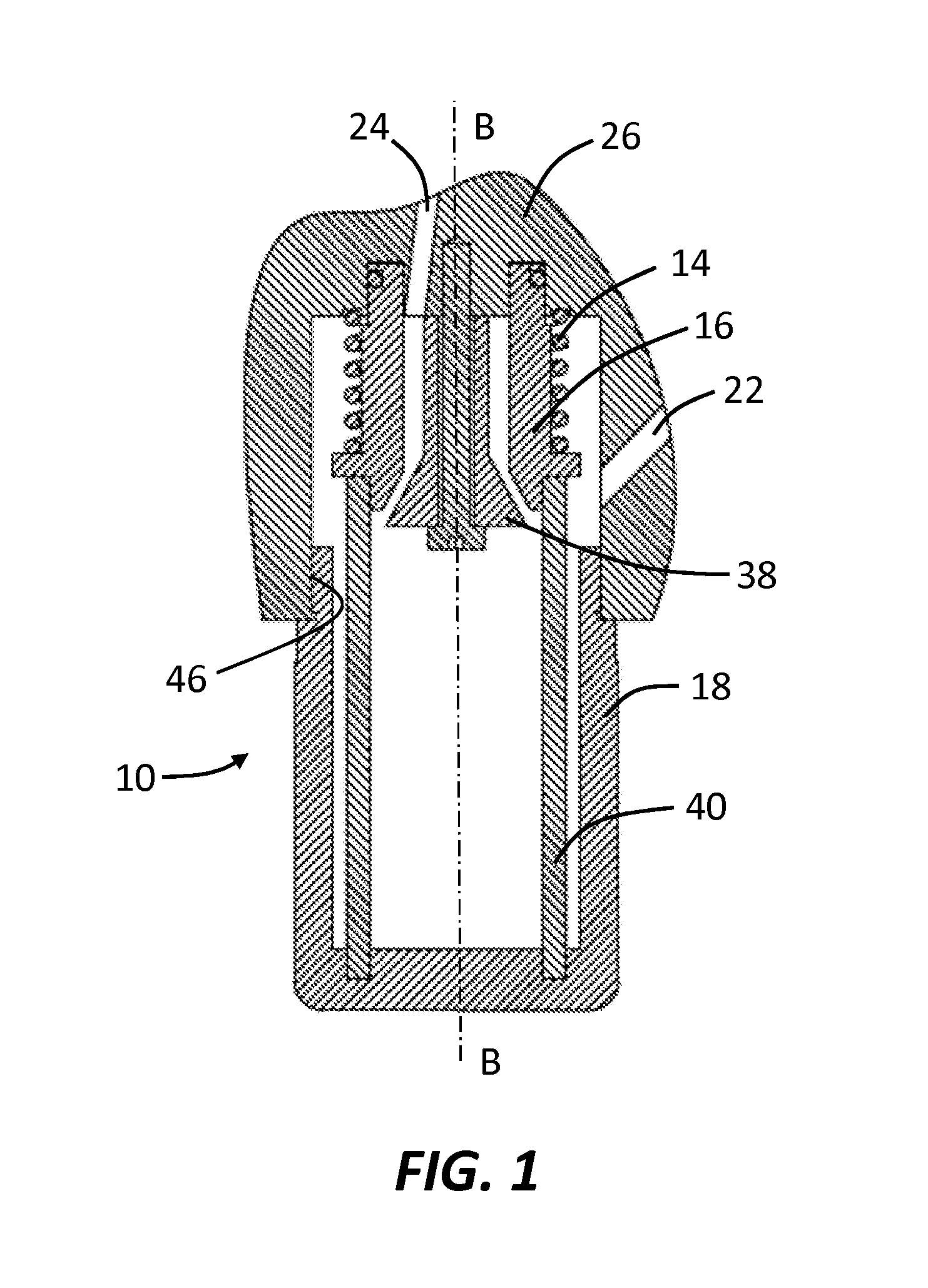
[0032]FIG. 3 is a cross-sectional view of a filter installation tool 80 with improved features and functionality. The first tool 80 can be used, for example and without limitation, to install a supply-line and / or a return-line filter in an aircraft hydraulic actuation system. The first tool 80 can include an outer body portion 82 having a threaded outer surface 84, an inner body portion 86, a bearing assembly 88, and a longitudinal passageway 90 extending from an upper orifice 92 to a lower orifice 94 along a longitudinal axis D-D. The bearing assembly 88 can be disposed between the body portions 82, 86 to allow for relative rotational motion between the body portions 82, 86. A more detailed view of the outer body portion 82 is shown in FIG. 4, and a more detailed view of the inner body portion 86 is shown in FIG. 5.

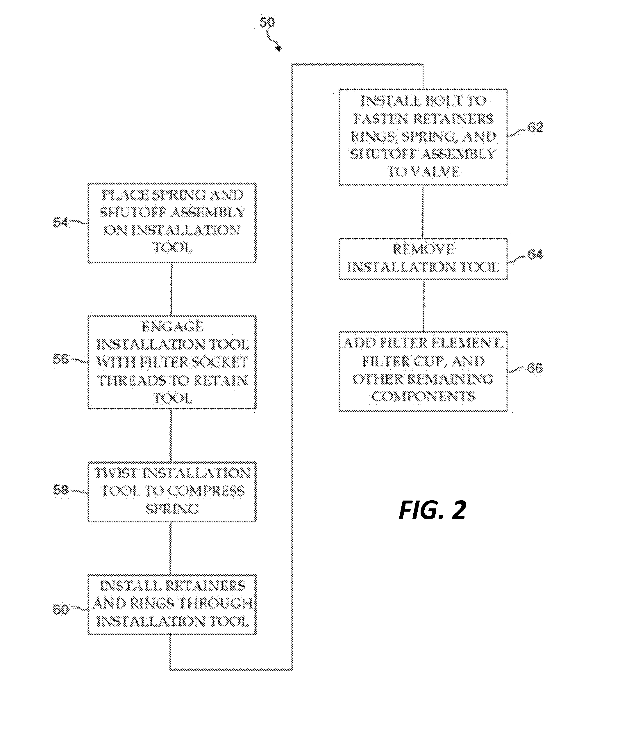
[0033]The first installation tool 80 can function similarly to the installation process described in the method 50 while improving on at least one shortcoming of convent...

second embodiment

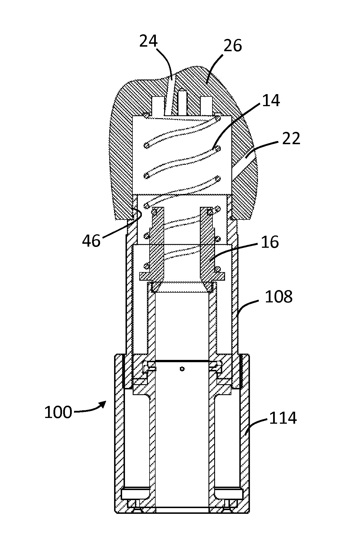
[0036]FIG. 6 is a cross-sectional view of a filter installation tool 100 that also demonstrates improved features or function. The second tool 100 can be used, for example and without limitation, to install a supply-line filter and / or return-line filter in an aircraft hydraulic actuation system. The second tool 100 can include an inner body portion 102 having an upper orifice 104, a lower orifice 106, an upper piece 102A (shown in greater detail in FIG. 9), and a lower piece 102B (shown in greater detail in FIGS. 12A and 12B), an intermediate body portion 108 (shown in greater detail in FIG. 10) having a first outer threaded surface 110 and a second outer threaded surface 116, a bearing assembly 112 for relative motion between the upper and lower pieces 102A, 102B of the inner body portion, and an outer body portion 114 (shown in greater detail in FIG. 11) having an inner threaded surface 118. Each of the body portions can be arranged about a central passageway 120 extending along a...


PUM


Abstract

An installation tool for one or more components of a fluid filter includes a first body portion configured to engage a filter socket to advance the tool and filter components into the socket, and a second body portion configured to apply a direct force to one or more filter components. The first and second body portions can rotationally move relative to each other, such that the filter components may not grind against the socket or other filter components, which can, among other things, reduce or eliminate the creation of foreign object debris and / or minimize the amount of human force required to install the filter components.

Description

CROSS-REFERENCE TO RELATED APPLICATIONS[0001]This application claims the benefit of U.S. Provisional Application Ser. No. 61 / 779,636, filed Mar. 13, 2013, the disclosure of which is incorporated herein by reference in its entirety.GOVERNMENT LICENSE RIGHTS[0002]This invention was made with government support under contract number N00019-06-C-0081 awarded by the Department of the Navy-Naval Air Systems Command. The government has certain rights in the invention.BACKGROUND[0003]1. Technical Field[0004]The present disclosure relates generally to fluid filtration components, including fluid filters and installation tools for fluid filters.[0005]2. Description of the Related Art[0006]Hydraulic actuators are used in a number of industries for many different applications. In particular, hydraulic actuators find use throughout many types of aircraft. Hydraulic actuation systems can include a number of moving parts in contact with circulating hydraulic fluid. If undesired foreign object debr...

Claims


Application Information

Patent Timeline
IPC IPC(8): B25B27/00B01D46/00
CPCB01D46/008B25B27/0042B25B27/026Y10T29/49718Y10T29/53848B01D46/88
Inventor SCHROEDER, RYAN JOSEPH
Owner EATON INTELLIGENT POWER LIMITED
Learn More