Step device for vehicle

Active Publication Date: 2021-03-11
AISIN SEIKI KK +1
View PDF13 Cites 0 Cited by
  • Summary
  • Abstract
  • Description
  • Claims
  • Application Information

AI Technical Summary

Benefits of technology

[0008]In the above aspect, however, the movable step does not put a load on the sliding door while the engaging part of the coupling member moves through the terminal end region on the closing side as the closing-

Problems solved by technology

As a result, the force required to ope

Method used


Image

  • Step device for vehicle
  • Step device for vehicle
  • Step device for vehicle

Examples


Example

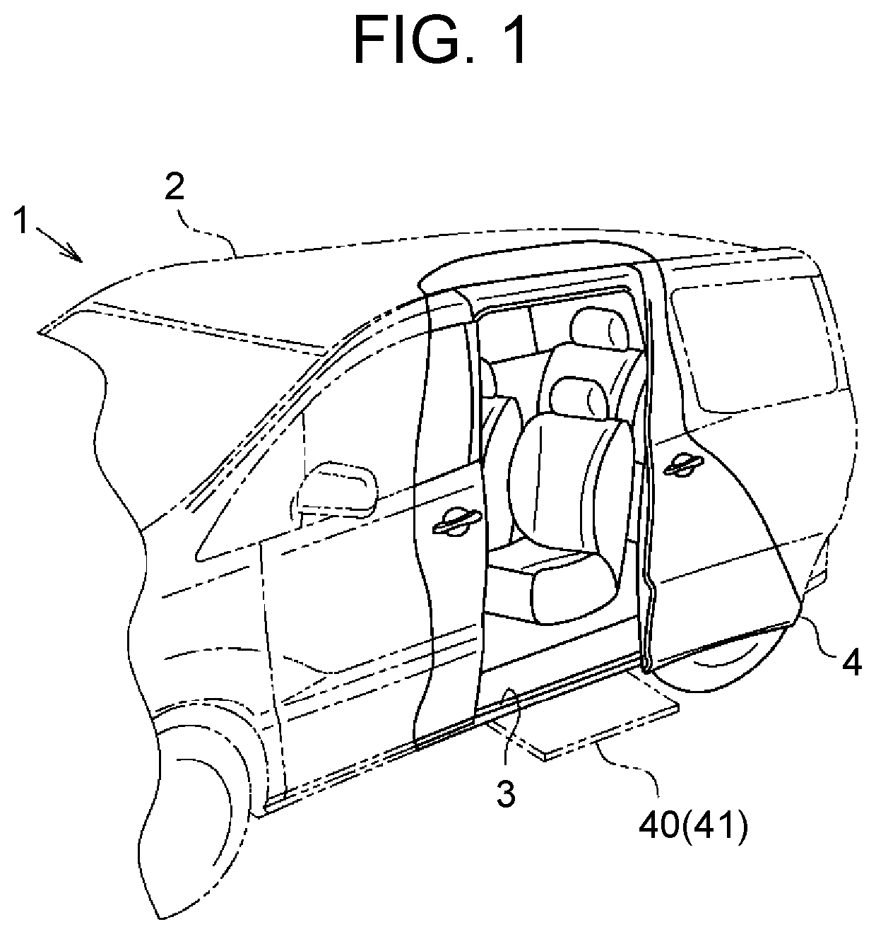
[0064]One embodiment relating to a step device for a vehicle will be described below in accordance with the drawings. As shown in FIG. 1, a vehicle 1 of this embodiment includes a sliding door 4 that can move in a vehicle front-rear direction (a left-right direction in FIG. 1) so as to open and close a door opening 3 provided in a side surface of a vehicle body 2.

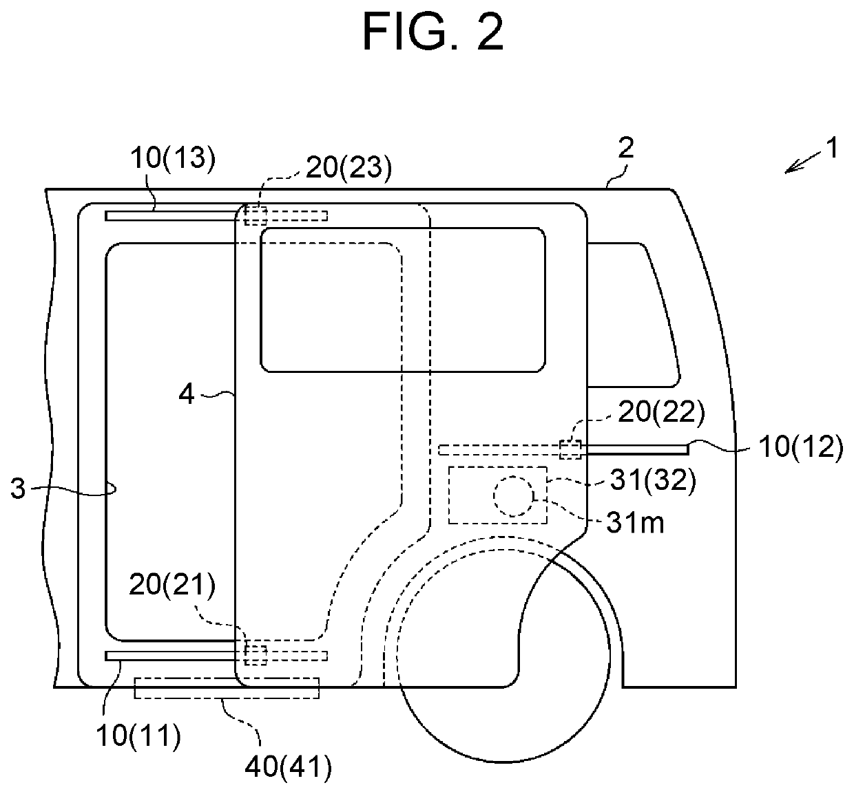
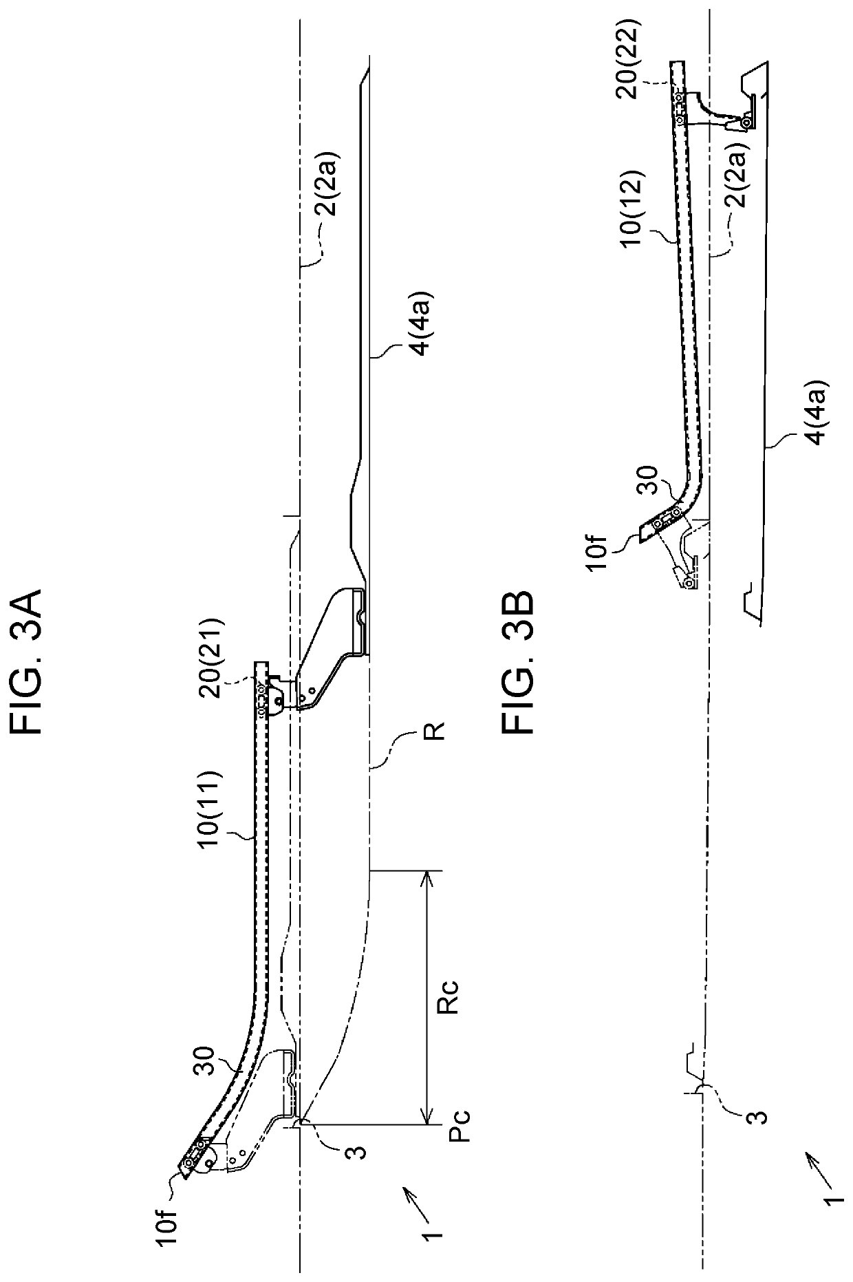
[0065]Specifically, as shown in FIG. 2, the vehicle 1 of the embodiment has a plurality of guide rails 10 that is provided on the side surface of the vehicle body 2 and extends in the vehicle front-rear direction. In particular, the vehicle 1 of the embodiment is provided with a lower rail 11 disposed at a lower edge of the door opening 3, a center rail 12 disposed on a rear side of the door opening 3, and an upper rail 13 disposed at an upper edge of the door opening 3. Further, each of these guide rails 10 has a guide roller unit 20 coupled thereto that can slide along an extension direction of the guide rail 10. In the v...


PUM


Abstract

A step device for a vehicle includes a movable step and a coupling member. The movable step includes a guide rail. The coupling member is configured to cause the movable step to move from a deployed position to a retracted position as a engaging part comes into sliding contact with a side wall of the guide rail that is located on an inner side in a vehicle width direction and, while pressing the side wall, moves inside the guide rail in a direction of closing a sliding door. The guide rail is configured such that a terminal end region on a closing side including a terminal end position at which the engaging part is located when the sliding door is fully closed constitutes a closing-side free running zone in which the engaging part does not press either of the side walls.

Description

CROSS-REFERENCE TO RELATED APPLICATION[0001]This application claims priority to Japanese Patent Application No. 2019-164028 filed on Sep. 9, 2019, incorporated herein by reference in its entirety.BACKGROUND1. Technical Field[0002]The present disclosure relates to a step device for a vehicle.2. Description of Related Art[0003]There are step devices for vehicles in which a movable step provided under a door opening is moved in a vehicle width direction in conjunction with opening and closing of a sliding door. For example, in the step device described in Japanese Patent Application Publication No. 2007-269086, a movable step is coupled to a sliding door through a guide member that is provided on a lower surface of the movable step and a coupling member that has a sliding member guided by the guide member. Thus, the movable step is moved to a deployed position on an outer side in a vehicle width direction in conjunction with the sliding door as the sliding door opens toward a vehicle r...

Claims


Application Information

Patent Timeline
IPC IPC(8): B60R3/02E05F15/41
CPCB60R3/02B60J5/06E05F15/41B60R3/007E05D15/101E05Y2800/102E05Y2900/53E05Y2900/531E05Y2400/55
Inventor OJI, YOSHIHIRONOMURA, KEISUKEKAZAMA, SHINJIHIBI, KAZUHIROIKEDA, KAZUHIRO
Owner AISIN SEIKI KK
Why Eureka
Try Eureka