[0010]A seal member is disclosed herein for forming a seal at the juncture of a coaxial cable connector and a terminal, wherein the coaxial cable connector is secured to an end of a coaxial cable. The seal member can be advantageously mounted on the connector to form a seal member / connector
assembly, or seal-connector
assembly. The connector of the seal-connector
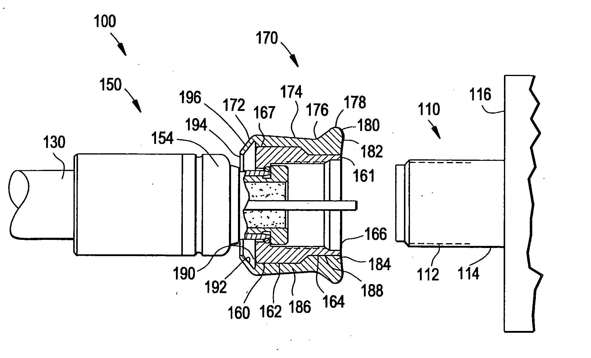
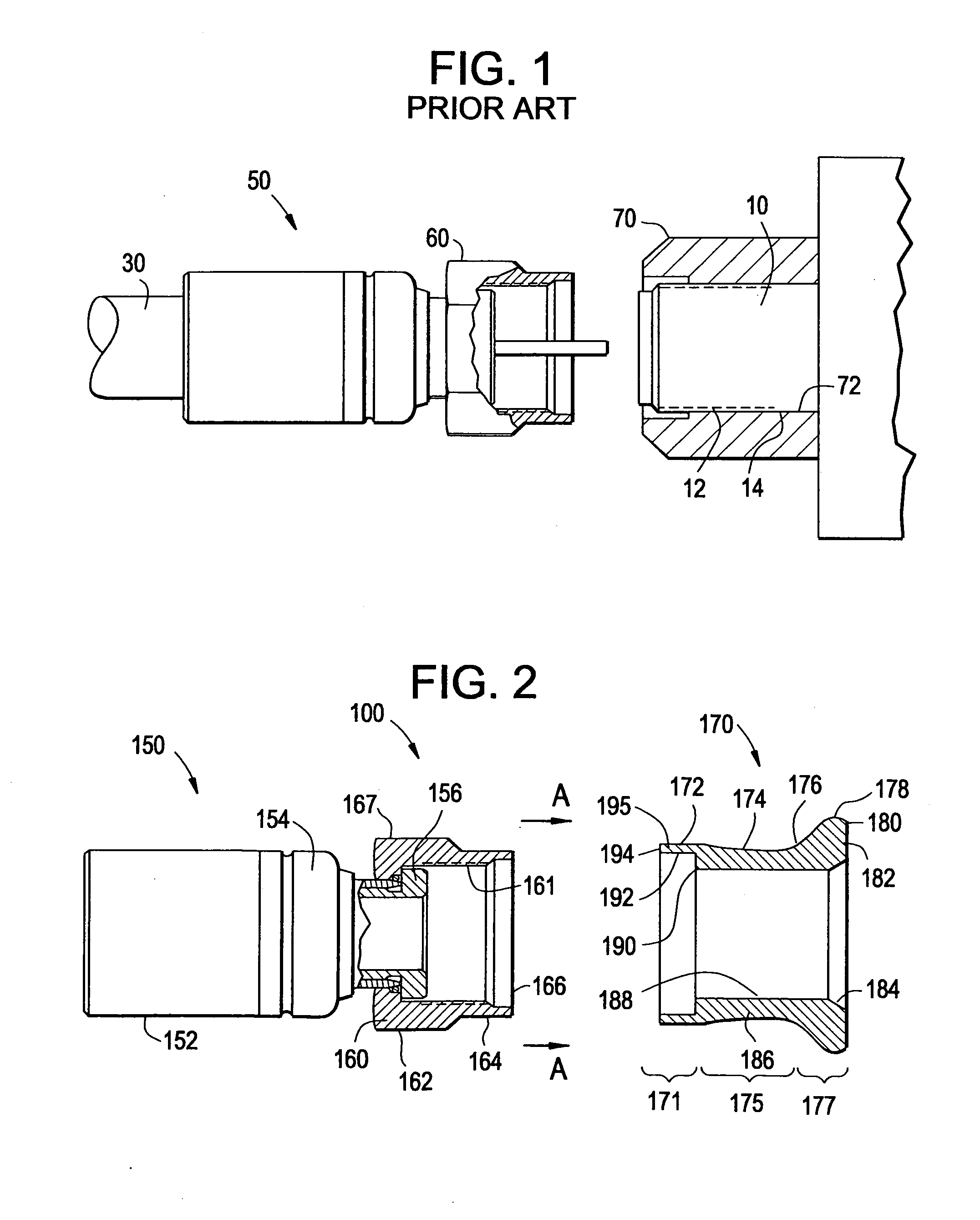
assembly can be secured to the coaxial cable prior to connection of the seal-connector assembly with the terminal. The seal member can be slid over the connector and into contact with the terminal while maintaining contact with the connector. Preferably, the entire seal member is slid over, i.e. translates over, the connector and into contact with the terminal. The seal member can thus provide a 360° environmental seal around the connector-terminal junction. In some embodiments, the seal member is slidably mounted on a coupler, such as a nut, of the connector. The seal member is generally tubular with an inner surface having a first inner
diameter, located at least at a first axial position on the seal member, which is smaller than an outer
diameter of the terminal, and the inner surface having a second inner
diameter, located at least at a second axial position on the seal member, which is smaller than an outer diameter of the terminal, wherein the first and second diameters may be equal or different, and wherein the first and second axial positions may be equal or different. In the deployed position, the inner surface of the seal member contacts the connector and forms a 360° seal thereat, and the inner surface of the seal member contacts the terminal and forms a 360° seal thereat. In some embodiments, the seal member has a uniform tubular wall thickness. In other embodiments, the seal member has a
variable thickness wall; in some of these embodiments, the seal member has a first portion having a first wall thickness which is larger (i.e. thicker) than the wall thickness of another portion of the seal member, and preferably the first portion is disposed at or
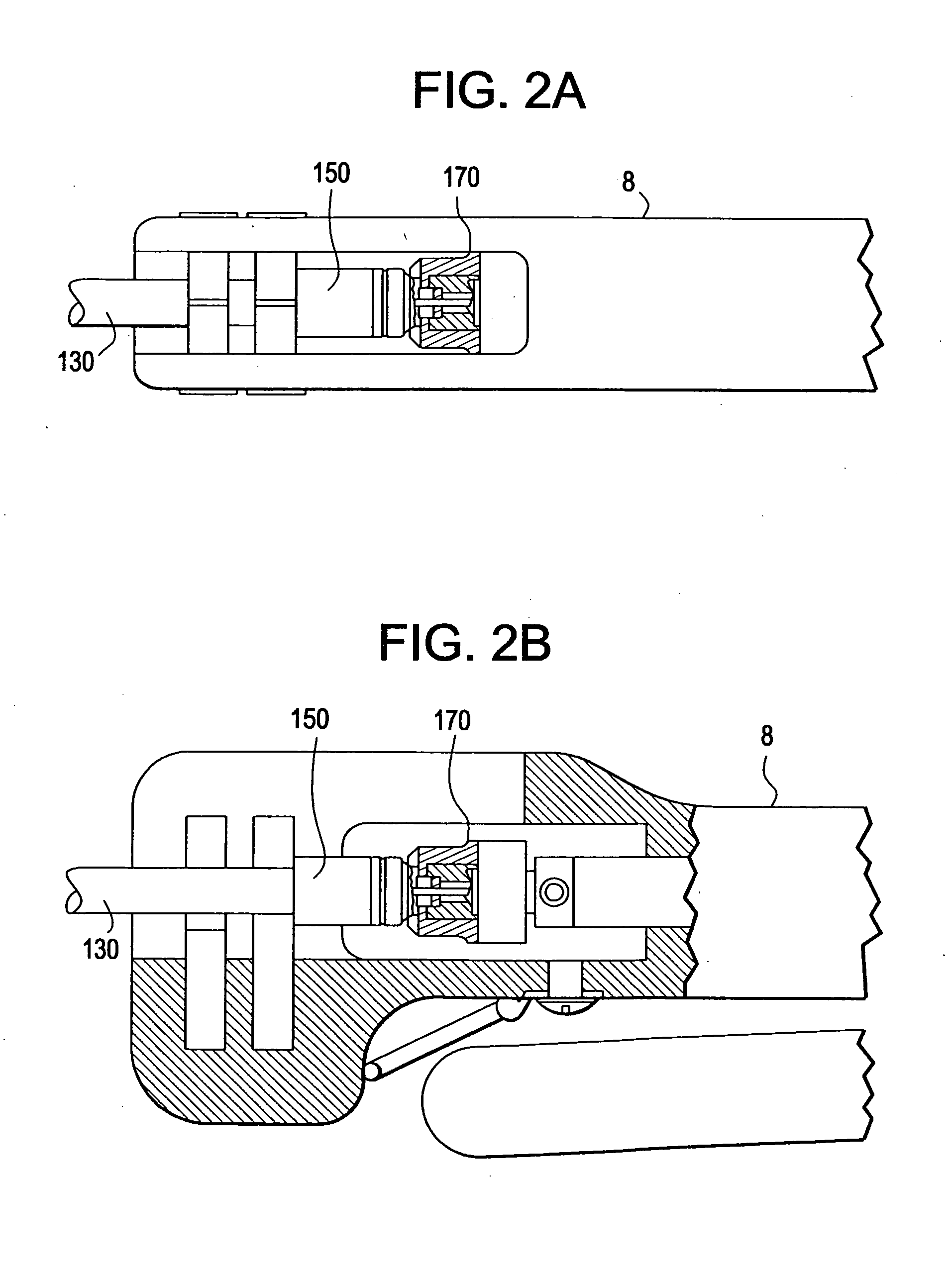
proximate a front end of the seal member, wherein “front” is the direction in which the seal member would face toward the terminal and “back” is the direction in which the seal member would face toward the coaxial cable, wherein such first portion can be advantageously provided to reduce the force required to slide the seal member over the coaxial connector. In accordance with one embodiment of the present invention, a method of connecting a coaxial connector and a terminal includes providing a coaxial connector comprising a coupler, the coupler having a seal member in contacting relationship with the coupler such that the seal member is coaxial with the coupler about a longitudinal axis, affixing the coupler to the terminal and after the coupler is affixed to the terminal, sliding the seal member longitudinally toward, and into contact with, the terminal.

