Sole support

a technology of sole support and support plate, which is applied in the field of sole support plate, to achieve the effect of convenient exercise for users

Pending Publication Date: 2021-09-23
ROBANOMIMI INC
View PDF0 Cites 2 Cited by
  • Summary
  • Abstract
  • Description
  • Claims
  • Application Information

AI Technical Summary

Benefits of technology

[0009]The use of the sole support by the user with the toe deformity makes it easier for the user to exercise.

Problems solved by technology

This is accompanied by pain when the toe is pressed by standing or walking.
For this reason, it is one of the biggest obstacles, especially when performing rehabilitation of paralyzed patients.

Method used


Image

  • Sole support
  • Sole support
  • Sole support

Examples


first embodiment

[0031](Overview)

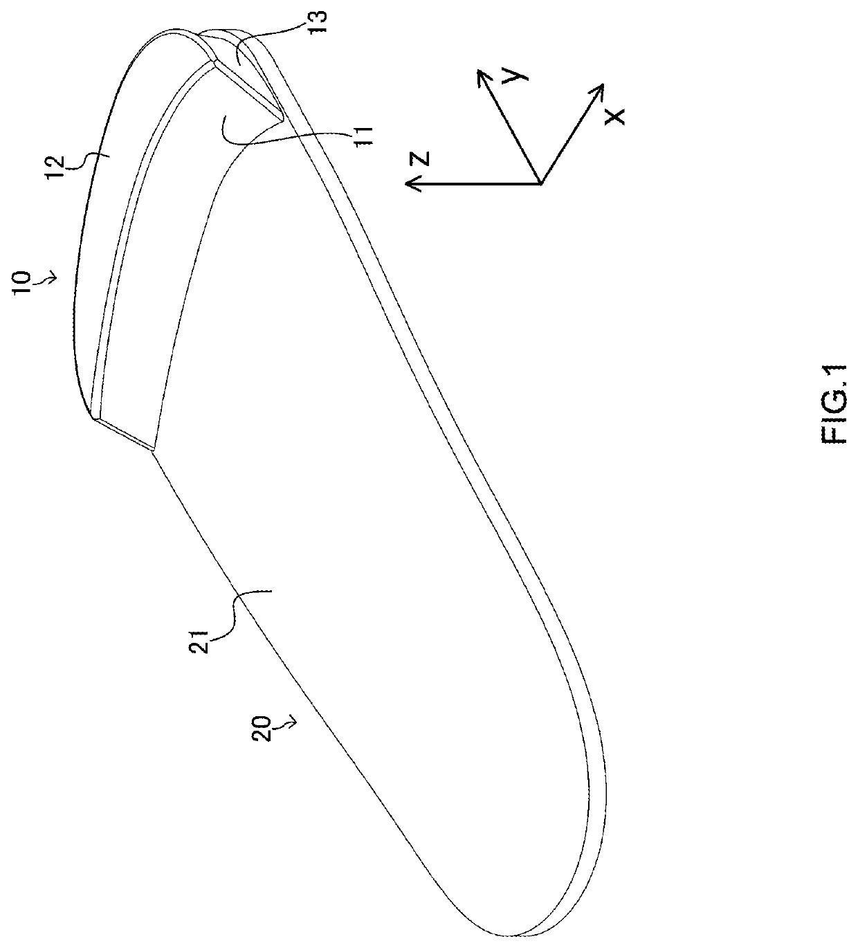
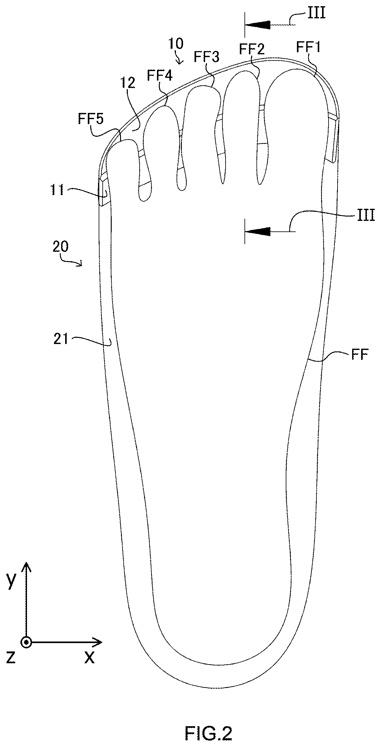
[0032]A sole support of a first embodiment constitutes at least a part of a support surface that supports a sole.

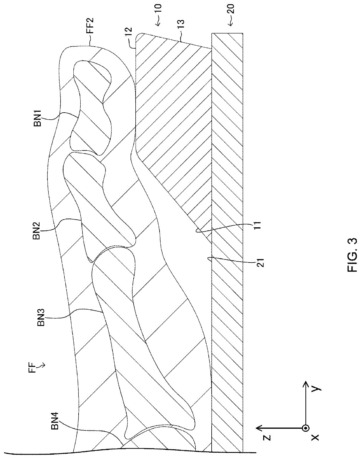
[0033]The sole support includes a high portion that constitutes a part of the support surface under at least a part of a distal phalange at a higher position than a part of the support surface under a proximal joint of a proximal phalange for each toe so that a proximal joint of the distal phalange is above the proximal joint of the proximal phalange in each toe.

[0034]According to this, the proximal joint of the distal phalange is located above the proximal joint of the proximal phalange for each toe. This makes it possible to bring the distal joint of the proximal phalange for each toe closer to a state in which the distal joint is extended. Further, a ratio of a force applied to the tip portion of each toe to a total force applied to the sole can be reduced.

[0035]Thus, according to the sole support, an excessive force to be applied to the tip portion of ...

second embodiment

[0108]Next, a sole support of a second embodiment will be described. The sole support of the second embodiment differs from the sole support of the first embodiment in that the top surface of the sole support has unevenness. The following is a description focusing on the differences. In the description of the second embodiment, the one with the same reference sign as used in the first embodiment is the same or substantially the same one.

[0109]As illustrated in FIGS. 12 to 18, the sole support 10A of the second embodiment includes a top surface 12A instead of the top surface 12 of the first embodiment.

[0110]FIG. 12 is a right back upper perspective view of the sole support 10A. FIG. 13 is a plan view of the sole support 10A. FIG. 14 is a bottom view of the sole support 10A. FIG. 15 is a front view of the sole support 10A. FIG. 16 is a back view of the sole support 10A. FIG. 17 is a right side view of the sole support 10A. FIG. 18 is a left side view of the sole support 10A.

[0111]As i...

third embodiment

[0117]Next, a sole support of a third embodiment will be described. In this example, the sole support may be referred to as a three-dimensional mallet toe corrector or a three-dimensional structure pad.


PUM


Abstract

A sole support constitutes at least a part of a support surface configured to support a sole. The sole support includes a high portion that constitutes a part of the support surface under at least a part of a distal phalange at a higher position than a part of the support surface under a proximal joint of a proximal phalange for each toe so that a proximal joint of the distal phalange is above the proximal joint of the proximal phalange in each toe.

Description

CROSS-REFERENCE TO RELATED APPLICATION[0001]This application is a continuation application of International Application No. PCT / JP2020 / 40563, filed on Oct. 29, 2020 and designated the U.S., which claims priority to Japanese Patent Application No. 2020-027567, filed on Feb. 3, 2020, the entire contents of each are incorporated herein by reference.FIELD[0002]The present disclosure relates to a sole support.BACKGROUND[0003]As described in Patent Document 1, a three-point support type toe orthosis used for a toe with a fracture in a distal phalange is known. The toe orthosis includes a proximal portion that contacts the toe under a middle phalange, a distal portion that contacts the toe under the distal phalange, and a toe backrest that contacts the toe over a proximal joint (in other words, a joint between the middle phalange and the distal phalange) of the distal phalange. This allows a state in which the proximal joint of the distal phalange of the toe with the fracture in the distal...

Claims


Application Information

Patent Timeline
Patent Type & Authority Applications(United States)
IPC IPC(8): A43B7/14
CPCA43B7/145A43B7/141A43B7/149A43B7/28A61F5/019A61F5/14
Inventor SUGAWARA, RYO
Owner ROBANOMIMI INC
Why Eureka
Try Eureka