Current sensing circuit disconnect device and method
What is Al technical title?
Al technical title is built by PatSnap Al team. It summarizes the technical point description of the patent document.
a current sensing circuit and disconnect device technology, applied in safety/protection circuits, emergency power supply arrangements, transportation and packaging, etc., to avoid spurious triggering, improve triac immunity, and improve false turn on immunity
Inactive Publication Date: 2021-09-23
SCHWARTZ ROBERT M
View PDF1 Cites 0 Cited by
Summary
Abstract
Description
Claims
Application Information
AI Technical Summary
This helps you quickly interpret patents by identifying the three key elements:
Problems solved by technology
Method used
Benefits of technology
The present invention provides a battery charging device with a snubber circuit to protect the triac from spurious triggering and improve its reliability against fast voltage transients. The snubber circuit consists of a resistor capacitor series pair connected in parallel with the triac that prevents spurious triggers and over voltage at turn off. Additionally, the invention includes a manual switch to disconnect the charging device from the mains when in a standby or idle mode of operation. The technical effects of the invention provide improved reliability of the battery charging device and prevention of spurious triggers and over voltage.
Problems solved by technology
This can be caused by electrical noise or other transient voltages from the mains.
Method used
Image
Click on the blue label to locate the original text in one second.
Reading with bidirectional positioning of images and text.
Examples
Embodiment Construction
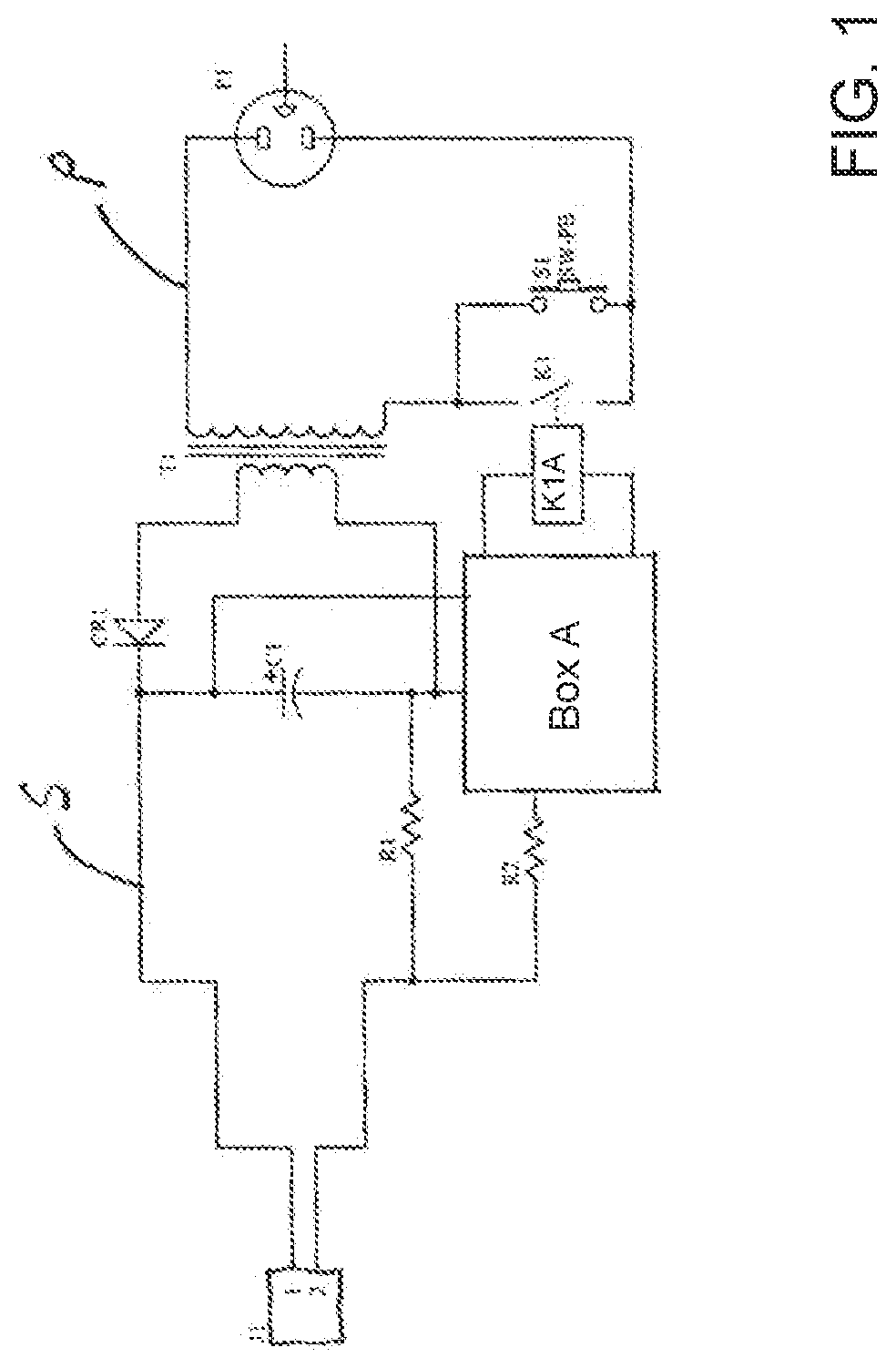
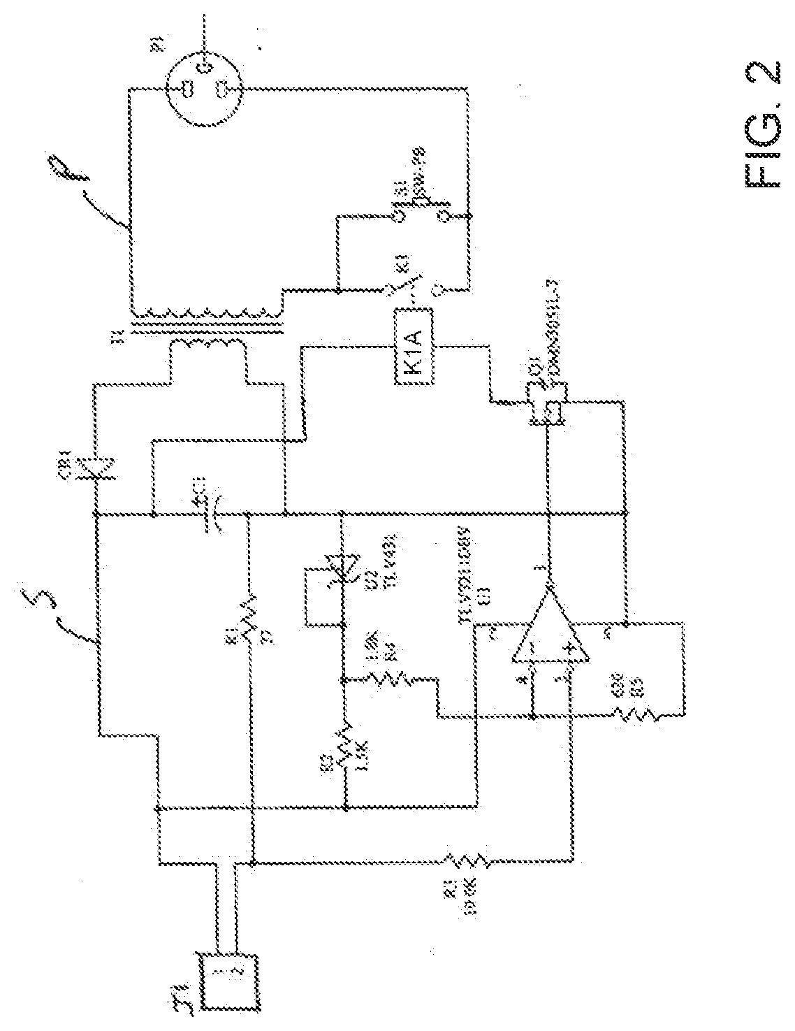
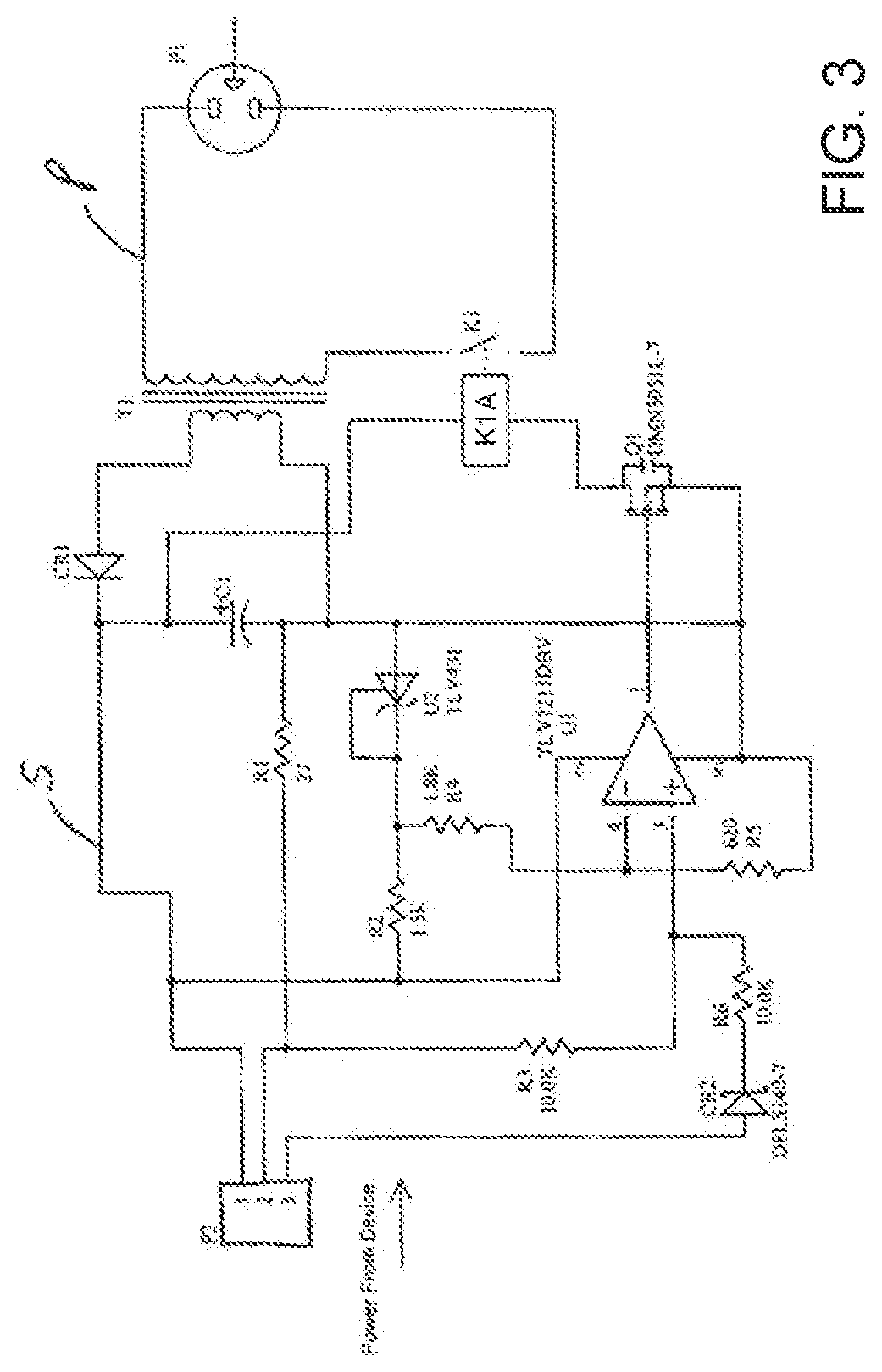
[0037]Referring now to FIG. 2, as disclosed in this application is a circuit similar to earlier circuits but more robust. CR1 represents a diode bridge to output direct current. The secondary circuit S operates on a stepped down voltage from the input voltage on the primary circuit P, as a result of transformer T1. Transformer T1 can also be a switching transformer where there would be a primary circuit P and a secondary circuit S.
[0038]Further as shown in FIGS. 9 and 10, a circuit showing a portion of the present invention includes a snubber circuit 200 in parallel with the triac 210 an optocoupler switch, which is opened to prevent current flow in the secondary side of the circuit and in the primary side, except for a small amount of current through the snubber circuit. The snubber circuit 200 includes, in series, a resistor 212 and a capacitor 214. An LED 250 is also shown as part of the optically isolated switch 205. The design of a snubber circuit involves compromises, includin...
PUM
Abstract
A device and method are provided for saving power and electricity in a charging device including external power supplies and battery chargers having a primary circuit and a secondary circuit where a switch is located in the primary circuit and a current sensing device in the secondary circuit to sense when there is a drop in current in the secondary circuit or no current in the secondary circuit because the load such as a cell phone or tablet is charged and when this occurs the switch in the primary circuit is opened and the primary circuit no longer draws power from the source of power until the switch in the primary circuit is closed by either a user activating a switch to reenergize the charging device, where the switch may be powered by an on-board battery to close the primary circuit, or where a control circuit is activated by a program in the load or device to be charged, such that the charging device will cycle on and off according to an external app program residing on the device to be charged or some other device not attached to the controller.
Description
CROSS-REFERENCE TO RELATED APPLICATIONS[0001]This application is a continuation application of co-pending U.S. patent application Ser. No. 16 / 102,303, filed Aug. 13, 2018, which was a continuation-in-part application of U.S. patent application Ser. No. 14 / 329,787, filed Jul. 11, 2014, now U.S. Pat. No. 10,050,459, dated Aug. 14, 2018 entitled Current Sensing Circuit Disconnect Device and Method, which claims the benefit of Provisional Application Ser. No. 61 / 845,179, filed Jul. 11, 2013 and which was a continuation-in-part application of U.S. patent application Ser. No. 13 / 908,217, filed Jun. 3, 2013, now U.S. Pat. No. 9,627,903, dated Apr. 18, 2017, which claims the benefit of Provisional Application Ser. No. 61 / 825,164, filed May 20, 2013 and which is a continuation-in-part application of U.S. patent application Ser. No. 13 / 892,509, filed May 13, 2013, now U.S. Pat. No. 9,035,604, dated May 19, 2015, which was a continuation-in-part application of U.S. patent application Ser. No. ...
Claims
Application Information
Patent Timeline
Application Date:The date an application was filed.
Publication Date:The date a patent or application was officially published.
First Publication Date:The earliest publication date of a patent with the same application number.
Issue Date:Publication date of the patent grant document.
PCT Entry Date:The Entry date of PCT National Phase.
Estimated Expiry Date:The statutory expiry date of a patent right according to the Patent Law, and it is the longest term of protection that the patent right can achieve without the termination of the patent right due to other reasons(Term extension factor has been taken into account ).
Invalid Date:Actual expiry date is based on effective date or publication date of legal transaction data of invalid patent.
Patent Type & Authority Applications(United States)