Vehicle body structure

a technology for vehicles and body parts, applied in the field of vehicle body structures, can solve the problems of not being able to prevent the pillar body from entering the passenger compartment, and not being able to fully satisfy the purpose, and achieve the effect of reducing the degree of displacemen

Active Publication Date: 2021-09-30
HONDA MOTOR CO LTD
View PDF0 Cites 0 Cited by
  • Summary
  • Abstract
  • Description
  • Claims
  • Application Information

AI Technical Summary

Benefits of technology

[0011]The present invention makes it possible to provide a vehicle body structure capable of, when an excessive load is inputted into the vehicle body from the outside, absorbing the load while reducing the degree of the displacement to the passenger compartment side.

Problems solved by technology

Thus, it is not really a structure to fully satisfy the purpose of protecting the occupants in the passenger compartment.
Hence, the structure of patent document 2 has a problem that when an excessive load is inputted, it is not possible to prevent the pillar body from getting into the passenger compartment.

Method used


Image

  • Vehicle body structure
  • Vehicle body structure
  • Vehicle body structure

Examples


first embodiment

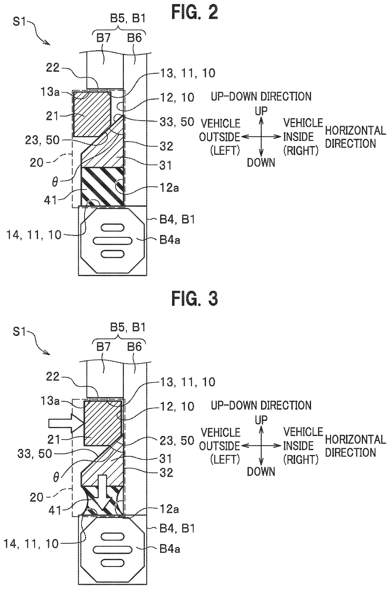
[0139]The operation after the impactor 21 is displaced toward the inner wall 12 is the same as or similar to the operation in the foregoing

[0140]In addition, as another example, the impactor 21 may be disposed on the upper standing wall 13 to be slidable on the upper-standing-wall wall surface 13a in the vehicle inside-outside direction via a rail-like structure (not illustrated) or the like.

[0141]With such a configuration, in the case where a load is inputted from the outside, the outer member B9 pushes the impactor 21, and the pushed impactor 21 is displaced on the rail-like structure toward the inner wall 12.

[0142]Receiving the inputted load, the impactor 21 is displaced on the wall surface of the upper standing wall 13 in the direction from the opening of the skeleton recessed portion 10 toward the inner wall 12 (in a horizontal direction).

[0143]The impactor 21 being displaced toward the inner wall 12 seeks to move in an obliquely upper right direction in the figure because the ...

fourth embodiment

[0198]Next, the present invention will be described in detail with reference to FIG. 9.

third embodiment

[0199]The present embodiment is a modification example of the foregoing

[0200]Hence, in the description, the same constituents as in the third embodiment are denoted by the same symbols, and repetitive description thereof is omitted.

[0201]A vehicle body structure S4 of the fourth embodiment has two crushing mechanisms 20 each including the slider 313 in the foregoing third embodiment and arranged side by side in the front-rear direction in one skeleton recessed portion 10.

[0202]The two crushing mechanisms 20 are not linked to each other, and each crushing mechanism 20 operates separately.

[0203]Next, a description will be given of operational advantages of the vehicle body structure S4 according to the present embodiment.

[0204]In the vehicle body structure S4 of the present embodiment, the two crushing mechanisms 20 are arranged side by side in the one skeleton recessed portion 10 in the state where the two crushing mechanisms 20 can operate separately.

[0205]This configuration in the ...


PUM


Abstract

Provided is a vehicle body structure in which when a load acts on an impactor, the impactor is moved toward an inner wall, a slider is moved along the inner wall by means of direction-changing unit, and in the case where the load acting on a crushing member via the slider exceeds a set value, the moving slider crushes the crushing member.

Description

CROSS-REFERENCE TO RELATED APPLICATION[0001]The present application claims the benefit of priority to Japanese Patent Application No. 2020-062846 filed on Mar. 31, 2020, the disclosures of all of which are hereby incorporated by reference in their entireties.TECHNICAL FIELD[0002]The present invention relates to a vehicle body structure capable of absorbing an excessive load inputted from the outside.RELATED ART[0003]To protect the occupants in the passenger compartment from the shock caused by a collision or the like, efforts have been made such as disposing a shock absorbing structure to absorb the shock, a skeleton structure configured not to be deformed by the shock to keep the internal space in the passenger compartment, and the like at various portions in the vehicle body.[0004]For example, Japanese Patent No. 4470494 (patent document 1) proposes a structure in which the center pillar itself moves to the passenger compartment side, which crushes an intermediate deformation allo...

Claims


Application Information

Patent Timeline
Patent Type & Authority Applications(United States)
IPC IPC(8): B62D21/15B62D25/02B62D25/04
CPCB62D21/157B62D25/04B62D25/025
Inventor HASEGAWA, ATSUSHIFUJII, TAKAYUKISAITO, YUMI
Owner HONDA MOTOR CO LTD
Why Eureka
Try Eureka