
Rotary Control Valve Having Minimized Internal Fluid Leak Rate When Closed

a technology of internal fluid leakage rate and rotary control valve, which is applied in the direction of machines/engines, engine components, mechanical equipment, etc., can solve the problems of inability to use rotary valves for that given application, considerable leakage around the control element still occurs, etc., and achieves the effect of minimizing the internal leakage ra

Active Publication Date: 2021-10-07
VECTOR HORIZON TECH LLC
View PDF8 Cites 0 Cited by
  • Summary
  • Abstract
  • Description
  • Claims
  • Application Information

AI Technical Summary

Benefits of technology

The present patent describes a rotary control valve that includes a valve body, a valve shaft, and a first control element. The valve can be moved between a closed position, in which it sealingly engages the valve seat, and an open position, in which it is spaced from the valve seat. The valve also includes a first pressure labyrinth and a second pressure labyrinth that work together to minimize the internal leak rate of the valve. The technical effects of this design include reducing the likelihood of leaks, minimizing pressure drop, and improving the stability of the valve's performance.

Problems solved by technology

However, in many cases, even when the control element is in the closed position (in sealing engagement with the valve seat), considerable leakage around the control element can still occur, particularly where the control element meets the valve shaft and / or the valve seat.
In turn, the rotary valves that experience this leakage have an internal leak rate (i.e., a closed internal leak rate) that is higher than an acceptable or threshold internal leak rate for a given application, such that those rotary valves are no longer usable for that given application.

Method used


Image

  • Rotary Control Valve Having Minimized Internal Fluid Leak Rate When Closed
  • Rotary Control Valve Having Minimized Internal Fluid Leak Rate When Closed
  • Rotary Control Valve Having Minimized Internal Fluid Leak Rate When Closed

Examples


Embodiment Construction

[0028]The present disclosure is directed to a rotary control valve that minimizes, if not virtually eliminates, the fluid leakage that occurs in conventional rotary control valves when those rotary control valves are closed. The rotary control valve disclosed herein is intended to be utilized with a vehicle (e.g., a diesel vehicle, a commercial vehicle) to, for example, control exhaust fluid flow recirculation (e.g., in an engine in a diesel vehicle), such that the rotary control valve minimizes fluid leakage during exhaust fluid flow recirculation. Nonetheless, it will be appreciated that the rotary control valve can be utilized in other industries, including, for example, oil & gas, food & beverage, fluid control, etc.

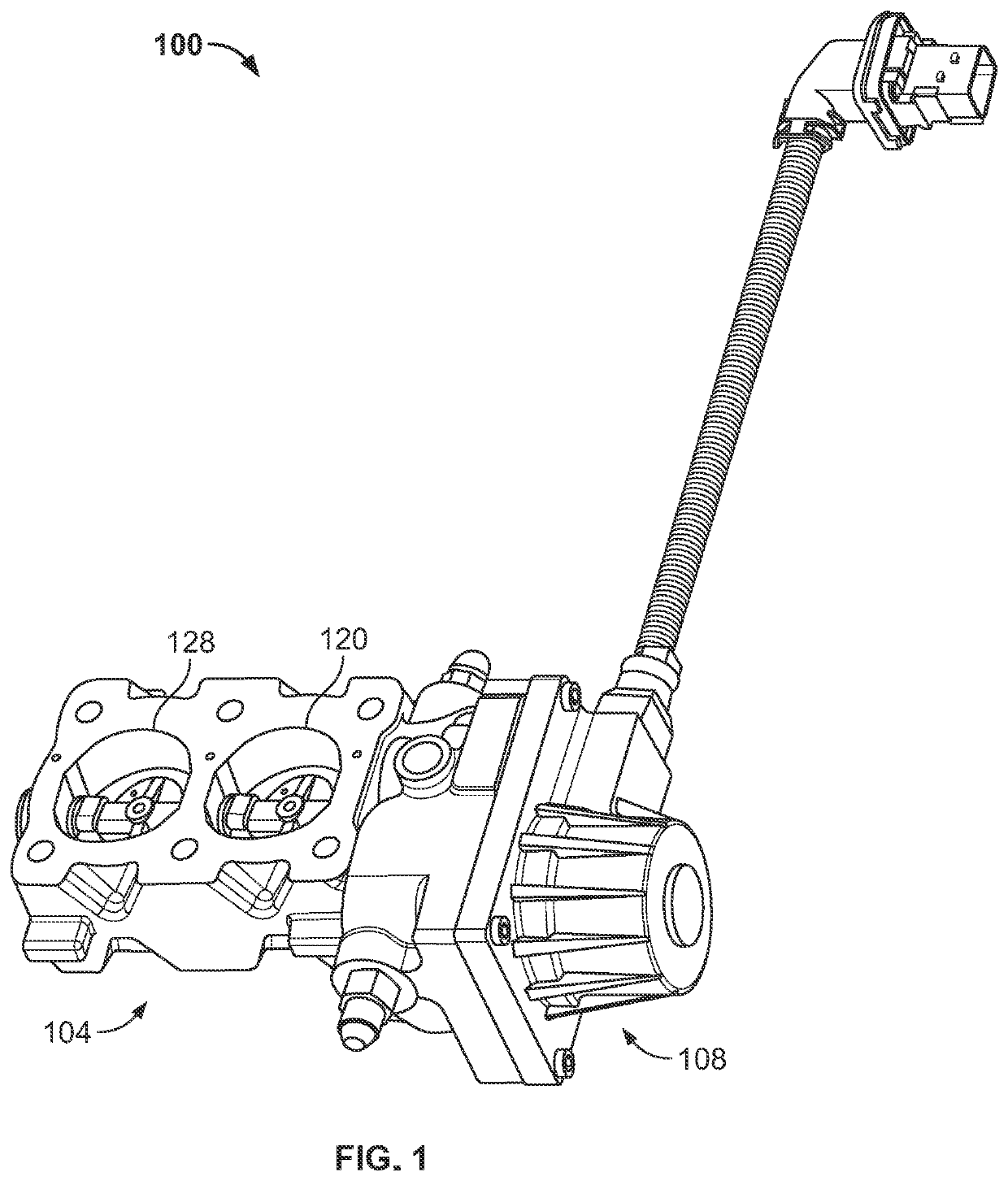
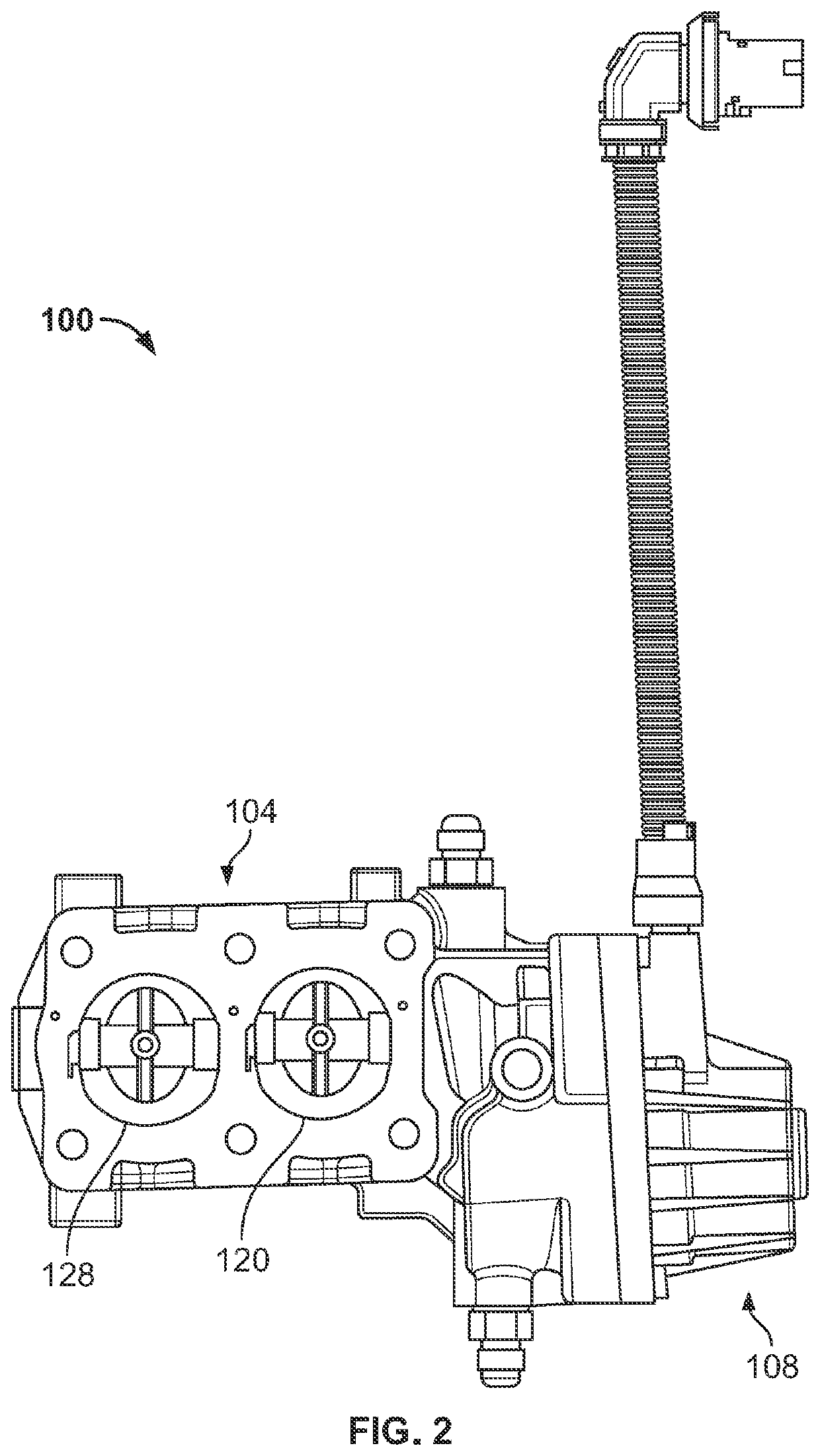
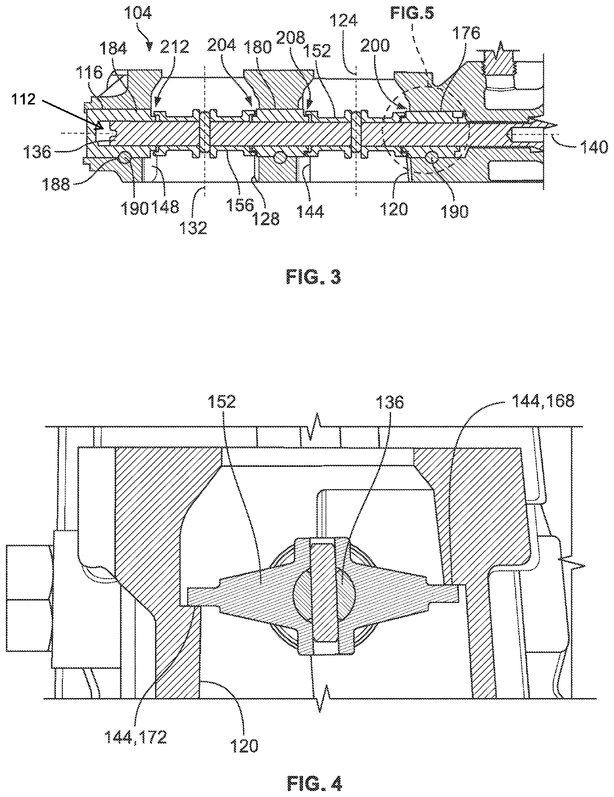
[0029]FIGS. 1-5 illustrate one example of a rotary control valve 100 constructed in accordance with the principles of the present disclosure. The rotary control valve 100 generally includes a valve body 104, an actuator 108 that is coupled to the valve body 104 (e.g....


PUM


Abstract

A rotary control valve that includes a valve body, a valve shaft disposed within a bore of the valve body, a first valve seat disposed within the valve body, a first control element carried by the valve shaft, and a first pressure labyrinth at least partially defined by the first control element. The first control element is movably disposed in the first opening between a closed position, in which the first control element sealingly engages the first valve seat, thereby closing the first opening, and an open position, in which the first control element is spaced from the first valve seat, thereby opening the first opening. When the first control element is in the closed position, the first pressure labyrinth is configured to cause a pressure drop in fluid flowing therethrough, thereby minimizing an internal leak rate of the rotary control valve.

Description

FIELD OF THE DISCLOSURE[0001]The present patent relates generally to rotary control valves and, in particular, to a rotary control valve that has a minimized internal fluid leak rate when closed.BACKGROUND OF THE DISCLOSURE[0002]Process control systems often employ rotary valves, such as ball valves, butterfly valves, eccentric-disk valves, eccentric-plug valves, etc., to control the flow of process fluids. Rotary valves typically include a valve trim assembly having a valve seat disposed in the fluid path and surrounding a flow aperture, and a control element (e.g., a disk, a ball, etc.) disposed in the fluid path and rotatably coupled to the body of the valve via a valve shaft. To control the flow of fluid through some rotary valves, the position of the control element may be varied from a closed position at which the control element is in sealing engagement with the valve seat, thereby preventing fluid flow through the flow aperture, to a fully open or maximum flow rate position ...

Claims


Application Information

Patent Timeline
Patent Type & Authority Applications(United States)
IPC IPC(8): F16K1/226
CPCF16K1/2268F16K1/223F16K1/32F16K1/36F16K1/44F16K1/465F16K47/08F16K1/224F02M26/70F02M26/72F02D9/106F02D9/1045F02D9/1095
Inventor BAASCH, OSWALDOHOLDER, STEFAN B.THOMAS, CASEYBIGLEY, JON A.
Owner VECTOR HORIZON TECH LLC
Learn More