
Method for simulating a flow in which a structure is submerged

a flow and structure technology, applied in the field of fluid mechanics, can solve the problems of methods that require significant calculation times and resources, methods that cannot come to a solution quickly, and require several iterations, and achieve the effect of rapid and accurate calculation

Pending Publication Date: 2021-10-07
CENT NAT DE LA RECHERCHE SCI +2
View PDF2 Cites 0 Cited by
  • Summary
  • Abstract
  • Description
  • Claims
  • Application Information

AI Technical Summary

Benefits of technology

The invention proposes a method for accurately and quickly calculating the flow lines in which an object is submerged. This is done by modelling the object using points called source points and calculating the interaction of these points with the environment. The interaction is determined using a method called "displaced flow" which quantifies the force applied to the object. The invention makes it possible to accurately determine the forces applied to the object and the direction in which the flow lines are oriented. This information is crucial for determining the performance and design of objects, such as aircraft, that are submerged in a fluid.

Problems solved by technology

However, these methods require very significant calculation times and resources.
In fact, these methods do not come to a solution quickly and require several iterations.
They are thus not suitable for carrying out calculations called “real-time” calculations of simulations of flow around a structure.

Method used


Image

  • Method for simulating a flow in which a structure is submerged
  • Method for simulating a flow in which a structure is submerged
  • Method for simulating a flow in which a structure is submerged

Examples


Embodiment Construction

[0038]The embodiments that will be described hereinafter are in no way limitative; in particular, variants of the invention can be implemented comprising only a selection of the characteristics described hereinafter, in isolation from the other characteristics described, if this selection of characteristics is sufficient to confer a technical advantage or to differentiate the invention with respect to the state of the prior art. This selection comprises at least one, preferably functional, characteristic without structural details, or with only a part of the structural details if this part alone is sufficient to confer a technical advantage or to differentiate the invention with respect to the state of the prior art.

[0039]In particular, all the variants and all the embodiments described are provided in order to be combined together in all combinations where there is no objection thereto from a technical point of view.

[0040]The different embodiments of the present invention comprise ...


PUM


Abstract

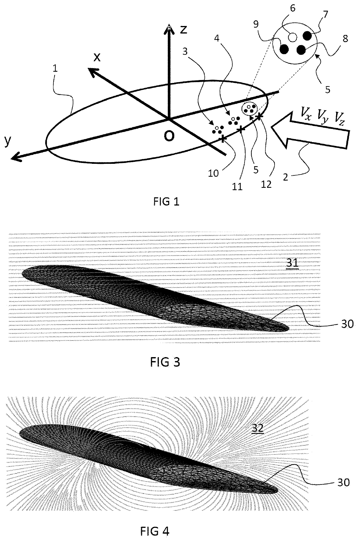
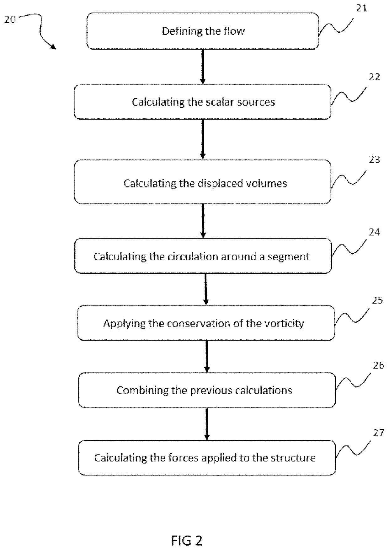
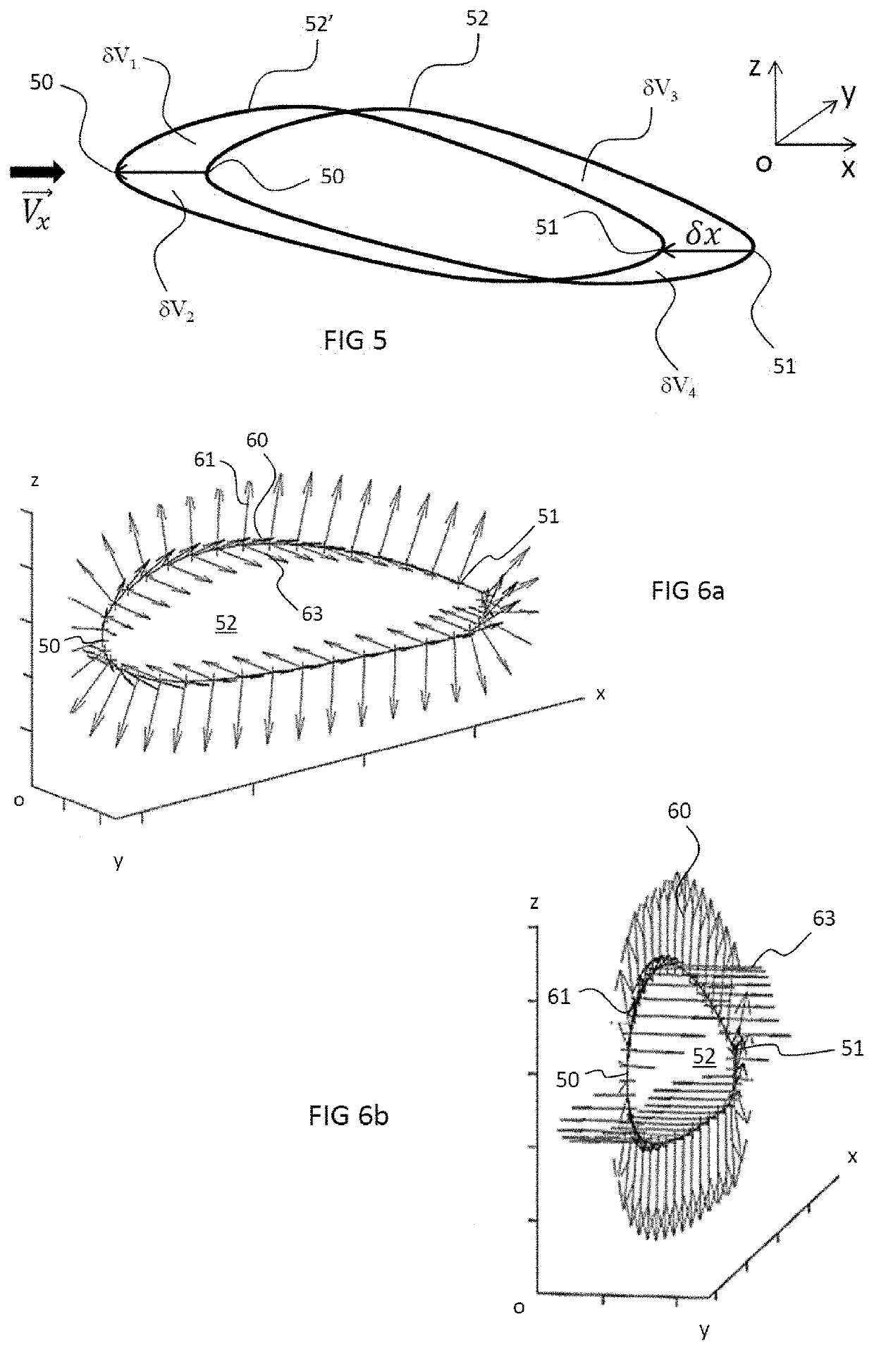
A method for simulating a flow in which a structure is submerged, the method being implemented by computer, and the behavior of the structure in the flow being modeled by radial and rotational sources generating a velocity field representing the flow around the structure.

Description

TECHNICAL FIELD[0001]The present invention relates in particular to the field of fluid mechanics. More particularly, the invention relates to a method for simulating a flow, for example a fluid flow, in which a structure is submerged.[0002]The invention can also be applied to a flow having the form of a wave.[0003]The invention relates in particular to determining forces being applied to said structure when it is positioned in the flow.STATE OF THE ART[0004]In the state of the art, there are several methods that make it possible to carry out flow simulations and simulations of interactions of said flow with an object or a structure, such as the methods known as CFD, for Computational Fluid Dynamics. These methods make very accurate calculations possible. However, these methods require very significant calculation times and resources. In fact, these methods do not come to a solution quickly and require several iterations. They are thus not suitable for carrying out calculations calle...

Claims


Application Information

Patent Timeline
Patent Type & Authority Applications(United States)
IPC IPC(8): G06F30/28G06F17/16
CPCG06F30/28G06F2111/10G06F17/16G06F30/15G06F30/20G06F2113/08
Inventor PLACKO, DOMINIQUEBARBOT, JEAN-PIERREGOURLAOUEN, SERGERIVOLLET, ALAIN
Owner CENT NAT DE LA RECHERCHE SCI
Learn More