Connectors for conduits

a technology of connecting wires and conduits, which is applied in the direction of tube connectors, medical devices, other medical devices, etc., can solve the problems of adverse impact and place the health of patients in danger

Pending Publication Date: 2021-10-21
FISHER & PAYKEL HEALTHCARE LTD
View PDF13 Cites 5 Cited by
  • Summary
  • Abstract
  • Description
  • Claims
  • Application Information

AI Technical Summary

Benefits of technology

[0007]It is therefore an object of the present invention to provide a connector or system of connectors which will go at least some way towards addressing the foregoing problems or which will at least provide the industry and / or public with a useful choice.
[0008]At times, an airflow source may need to be removed or replaced, or a patient interface may need to be removed from a breathing circuit, or other conduit forming a part of a breathing circuit may need to be replaced. If detaching the particular component (e.g. conduit or a patient interface) from the circuit is difficult or time consuming, such detachments may adversely impact on the maintenance or continued delivery of a gas therapy to a patient, or may become a frustration for the person making such a detachment. Further, in emergencies, a slow or difficult connection mechanism can potentially place the patient's health in danger. Thus, a conduit connector that provides a “quick-connect” or “quick-release” capability, and yet which facilitates the rapid and correct alignment and connection of a new connector, as well as facilitating interchangeability of components, can provide greater comfort and / or safety for the patient.
[0165]The at least one attachment arm may be cantilevered relative to the body of the connector to allow for flexibility of the attachment arm in at least a direction radial to the body of the connector optionally radially inward, outward or both.
[0196]Overlap of said cuff with a said breathing tube may facilitate for at least in part a relief of strain otherwise imparted to an engagement or connection made between the breathing tube and said first end or a component to be associated with said first end.
[0236]The at least one attachment arm may be cantilevered relative to the body of the connector to allow for flexibility of the attachment arm in at least a direction radial to the body of the connector optionally radially inward, outward or both.

Problems solved by technology

If detaching the particular component (e.g. conduit or a patient interface) from the circuit is difficult or time consuming, such detachments may adversely impact on the maintenance or continued delivery of a gas therapy to a patient, or may become a frustration for the person making such a detachment.
Further, in emergencies, a slow or difficult connection mechanism can potentially place the patient's health in danger.

Method used


Image

  • Connectors for conduits
  • Connectors for conduits
  • Connectors for conduits

Examples


Embodiment Construction

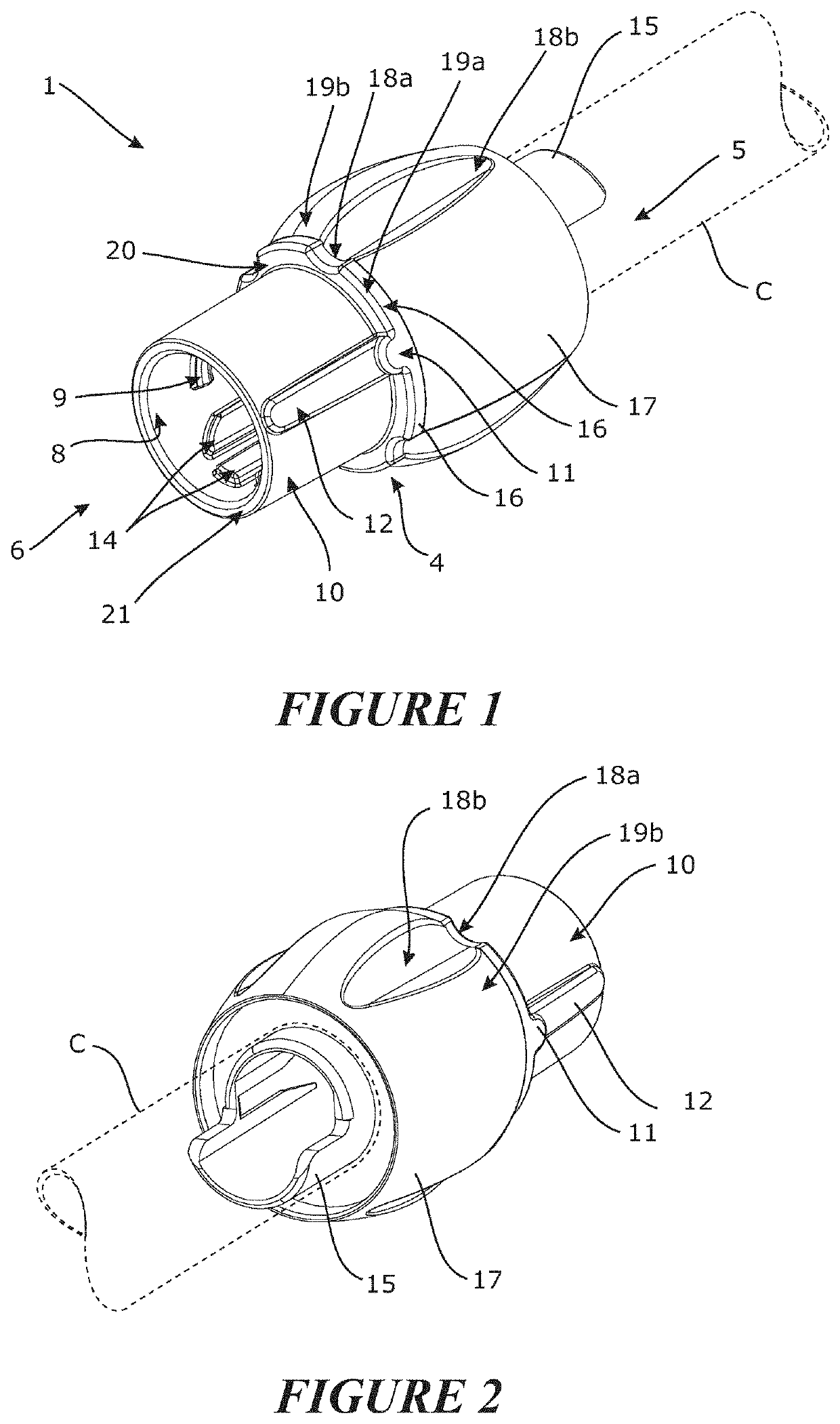
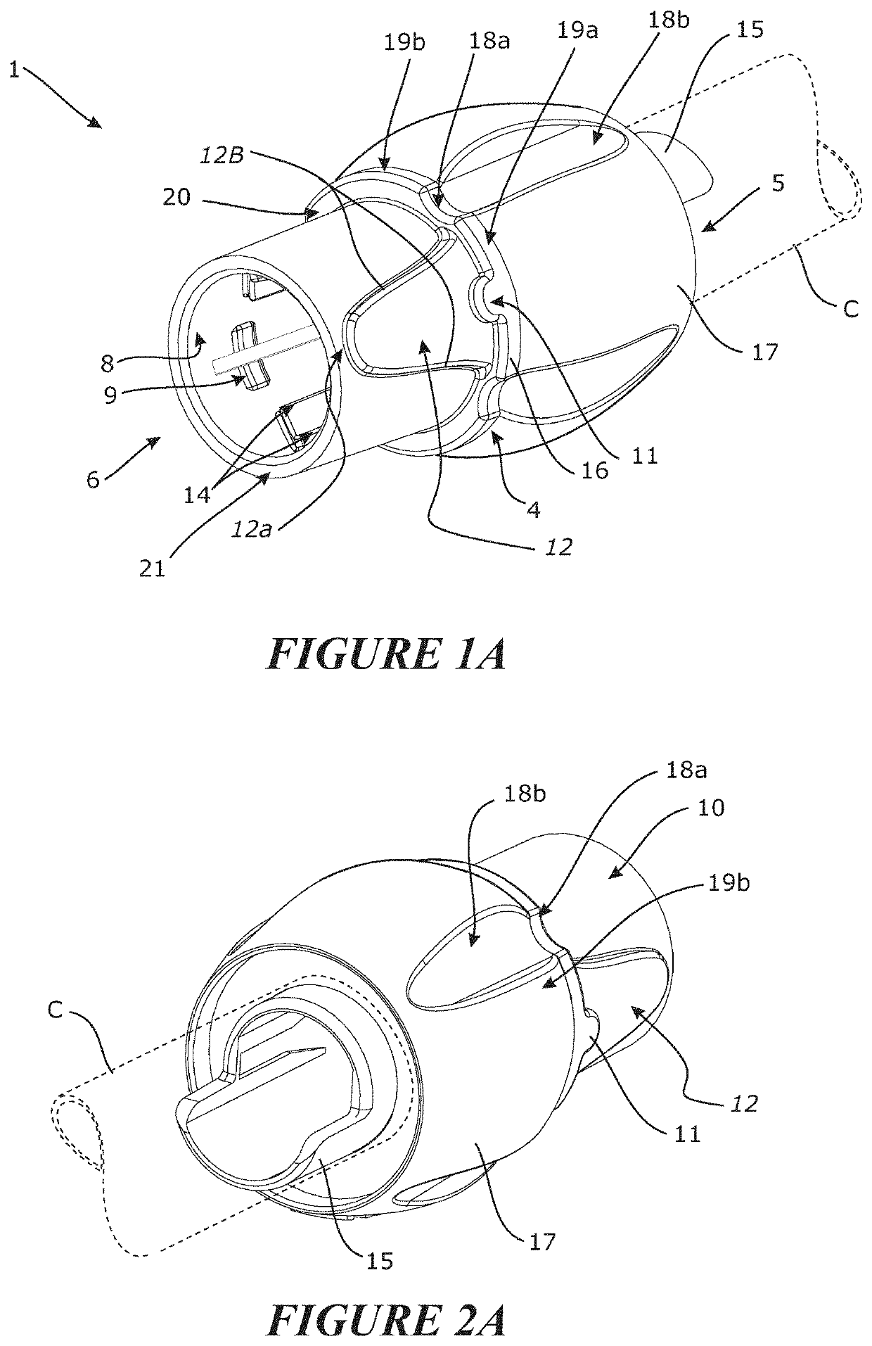
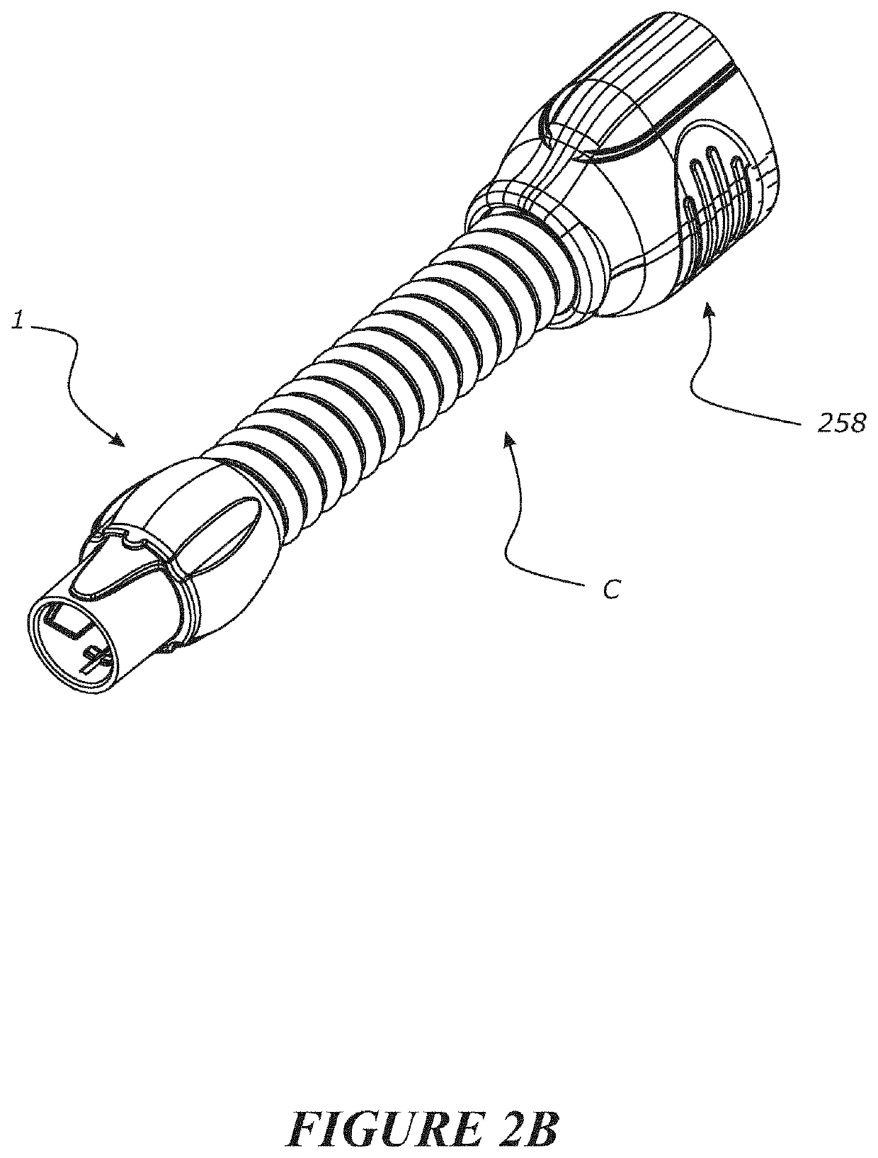
[0393]Provision of new and different connectors, particularly with a focus on improving useability as well as the correct alignment of connectors which are to be connected together, can improve patient safety in the successful and maintained delivery of gas therapies, such as delivery of humidified gas or other gas to a patient.

[0394]With reference to FIGS. 1-20, there is provided a connector 1 to be provided at a terminal end of a breathing conduit (indicated as C in the figures). The breathing conduit may be a medical breathing conduit. The connector 1 comprises a body 4 having a first end 5 and a second end 6. The body 4 itself internally defines a lumen 7 for the passage of gas therethrough between each of the first and second ends 5, 6. It will be appreciated that depending on the flow of gas through the lumen, the ends 5, 6 of the connector 1 may each be considered to be either upstream or downstream of the other end when placed into a breathing circuit, for example the direct...


PUM


Abstract

This invention relates to connectors to be provided into fluid communication or engagement either directly with, or via a component to be associated with, a terminal end of a breathing conduit. In at least one embodiment, the connector comprises a body having a first end and a second end, and an internal lumen for the passage of gas between the ends. The first end engageable with a terminal end of a conduit or a component to be associated therewith. The second end engageable with another connector. An internal surface of the body at the second end comprises internal connection features for connection with another connector to be received internally therein. An external surface of the body comprises one or more external alignment feature(s) for aligning the connector or another connection into an aligned orientation for connection therebetween.

Description

FIELD OF THE INVENTION[0001]The present invention relates to connectors for use in breathing circuits, more particularly, though not solely, to connectors to be used at the terminal end of a breathing conduit.BACKGROUND TO THE INVENTION[0002]Providing connectors for the terminal ends of breathing conduit is of importance for the continued and safe delivery of gas therapies to patients.[0003]For example, humidified or other gases may be transported via a series of conduits to provide for a breathing circuit, supplying the gas to a patient interface, such as for example to nasal cannula, mouthpieces, full face masks, nasal masks. Different conduits may be used in different parts of the breathing circuit.[0004]For example, conduit most closely associated with the patient may be of small diameter and may need to be more flexible, whilst conduit further away from the patient can be of a larger diameter, less flexible and may include electronics, such as heaters or other sensing circuitry...

Claims


Application Information

Patent Timeline
Patent Type & Authority Applications(United States)
IPC IPC(8): A61M16/08A61M16/10A61M16/16
CPCA61M16/0816A61M16/0875A61M16/1095A61M2205/584A61M16/0825A61M2205/3368A61M16/161A61M39/10A61M2039/1027A61M2039/1016F16L37/248
Inventor LAU, ANDREW CHI LUPPANARA, RICHARD DANIELGULLIVER, LAURENCECLARKSON, SOOJI HOPEKLENNER, JASON ALLANSALMON, ANDREW PAUL MAXWELLLAING, BRENT IAN
Owner FISHER & PAYKEL HEALTHCARE LTD
Why Eureka
Try Eureka