
Crankshaft

Pending Publication Date: 2021-12-30
BAYERISCHE MOTOREN WERKE AG
View PDF0 Cites 0 Cited by
  • Summary
  • Abstract
  • Description
  • Claims
  • Application Information

AI Technical Summary

Benefits of technology

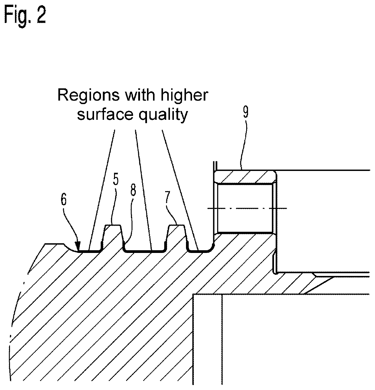
[0009]The use of different manufacturing processes makes it possible to increase the surface quality in the critical regions to a mean of the roughness depths Rz of less than 3 μm. Possible processes considered may in this case be, inter alia, grinding, finishing or else polishing (in the form of pure surface smoothing). All of the processes are associated with a significant smoothing of the surface in the critical region.
[0010]Investigations on a torsional pulse test stand have shown that the increase in the surface quality in critical regions, in particular in the region of the transition radii to the sprocket, from approximately Rz=7 μm to Rz less than 3 μm makes it possible to achieve a demonstrable increase in the torsio

Problems solved by technology

Results on a torsional pulse test stand show a limitation of the maximum possible torsional fatigue strength on account of possible incipient cracks in the critical region of the tra

Method used


Image

  • Crankshaft
  • Crankshaft

Examples


Example

DETAILED DESCRIPTION OF THE DRAWINGS

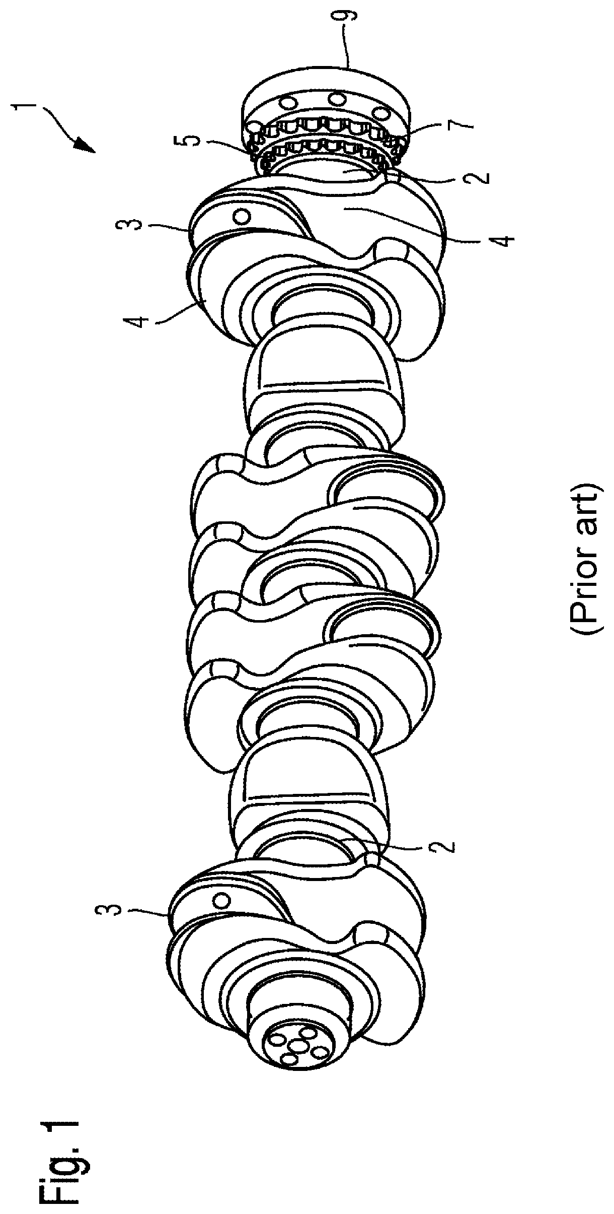
[0018]FIG. 1 shows a view of a crankshaft 1 according to the prior art. By way of example, the crankshaft 1 illustrated in FIG. 1 is a stock crankshaft for the 6-cylinder BMW in-line engine with the internal designation B57.

[0019]The crankshaft 1 comprises seven main bearings 2 and six crankpins 3, wherein the main bearings 2 and the crankpins 3 are connected via crank webs 4. The crank webs 4 can be configured with or without counterweights. A flange 9 is located at an end of the crankshaft 1. Located between the flange 9 and the adjacently arranged main bearing 2 in the present exemplary embodiment are two toothed rings 5, 7, which are manufactured together with the crankshaft 1, for chain drives (not illustrated).

[0020]In the series version, a crankshaft surface between the flange 9 and the main bearing 2 has a mean roughness depth of about 7 um. Results on a torsional pulse test stand have shown that there is a limitation of the maximum possib...


PUM

PropertyMeasurementUnit
Lengthaaaaaaaaaa
Depthaaaaaaaaaa
Surfaceaaaaaaaaaa

Abstract

The invention relates to a crankshaft (1) for a reciprocating piston internal combustion engine having at least two main bearings (2) a crank pin (3). Crankshaft flanges (4) are arranged between each of the main bearings and the crank pin and connect the main bearings to the crank pin. The crankshaft has at least one ring gear (5) spaced apart axially from a main bearing for a drive of a chain drive. A crankshaft surface between the main bearing and the first ring gear has an averaged roughness depth R z of less than 3 micrometres. Due to the configuration of the crankshaft according to the invention for a reciprocating piston internal combustion engine, higher torsional moments can be transmitted or the crankshaft can be designed to be lighter in the area having the higher surface quality.

Description

BACKGROUND AND SUMMARY OF THE INVENTION[0001]The disclosure relates to a crankshaft for a reciprocating-piston internal combustion engine.[0002]With regard to the technical field, reference is made for example to an existing method for increasing the fatigue strength of crankshafts for piston machines, in particular internal combustion engines, in the case of which crankshafts the transition radii between a crankpin and adjoining crank webs are subjected to a particular treatment. Said treatment consists of a hardening in the region of the transition radii to a hardening depth of 2-3 mm, along with a machining of the surface, proceeding from an intersection edge between a bearing point and a transition radius as far as the end of the run-on collar, to a roughness depth Rz greater than 6.3 μm.[0003]Furthermore, in an existing crankshaft that is provided in particular for air-compressing supercharged injection-type engines, the crankshaft comprises main bearing journals and connecting...

Claims


Application Information

Patent Timeline
IPC IPC(8): F16C3/08
CPCF16C3/08F16C2240/54F16C2220/44F16C2204/62F16C2360/22F16C2204/70F16C2220/70F16C2223/06F16C2204/64
Inventor KAMMERSTAETTER, STEFANREICHL, STEFAN
Owner BAYERISCHE MOTOREN WERKE AG
Learn More