
Method for continuous-path control
- Summary
- Abstract
- Description
- Claims
- Application Information
AI Technical Summary
Benefits of technology
Problems solved by technology
Method used
Image

Examples
Embodiment Construction
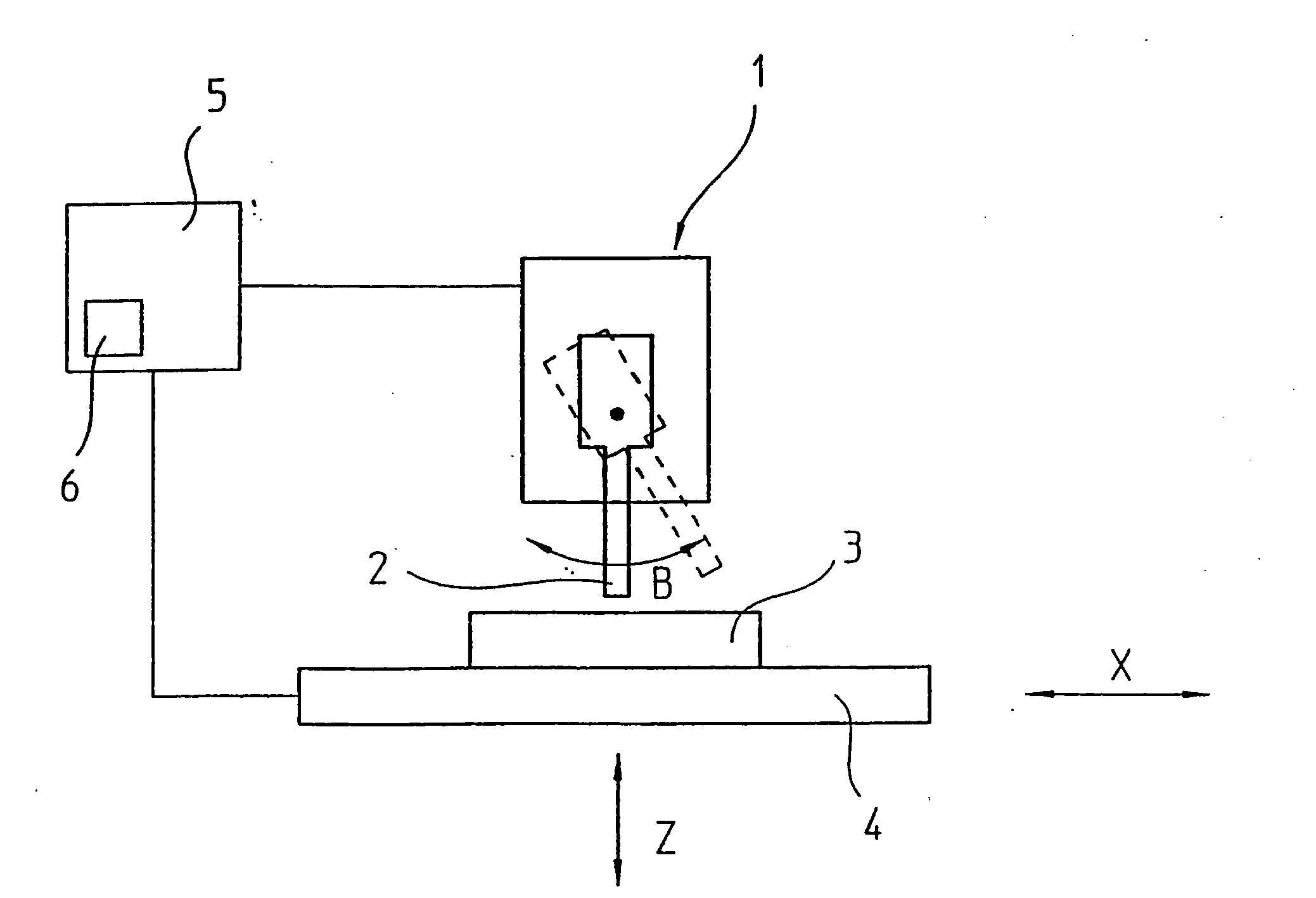
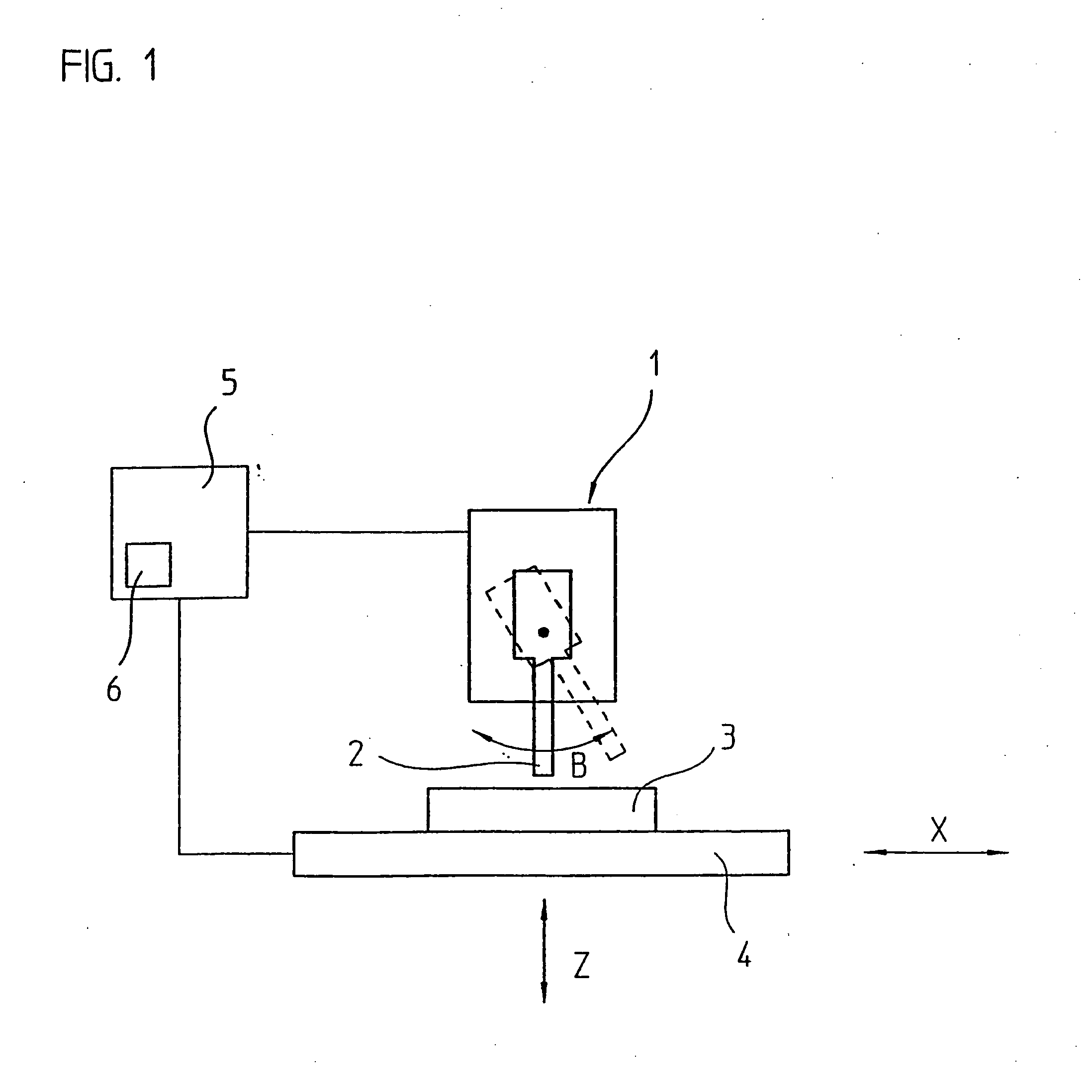
[0014]FIG. 1 shows a machine tool 1 having a tool 2. A workpiece 3 is mounted on a machining table 4. Workpiece 3 and tool 2 are movable relative to each other in several axes. Thus, linear axes in the X-direction and Z-direction are shown in the drawing; a third linear axis in the Y-direction is normal to the drawing plane. In a 5-axis milling machine, there are also two angle axes, of which the B-axis is shown in FIG. 1. Tool 2 is able to swivel about the direction of the Y-axis. A second angle axis A is obtained when machining table 4 is able to be tilted about the X-axis. Axes X, Y, Z, A, B are controlled by a numerical control 5 which, for example, is able to execute a parts program or receive and carry out individual commands by the machine-tool operator.
[0015]FIG. 1 illustrates that a movement of tool 2 about angle axis B causes the tip of tool 2 to shift with respect to workpiece 3. To simplify the programming of the machining of a workpiece in a plurality of axes X, Y, Z, ...
PUM
 Abstract
Description
Claims
Application Information