Image forming apparatus, method of controlling same, and storage medium
a technology of image forming apparatus and control method, which is applied in the direction of electrographic process apparatus, instruments, optics, etc., can solve the problems of pointless consumption of resources such as sheets and toner, and achieve the effect of not wasting the resources used for image formation
- Summary
- Abstract
- Description
- Claims
- Application Information
AI Technical Summary
Benefits of technology
Problems solved by technology
Method used
Image
Examples
case 1
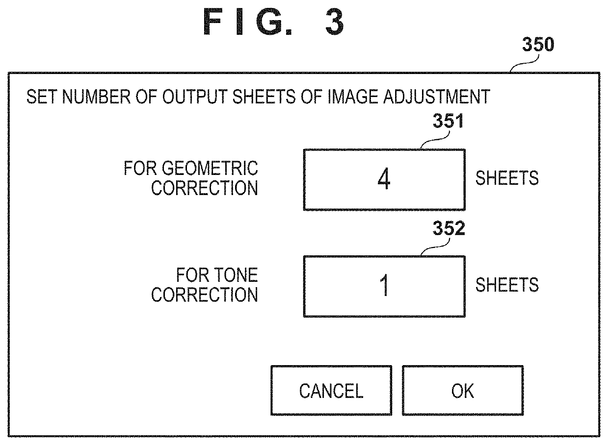
[0078]Case 1 is an example of output of a correction chart in a case where N1=4 and N2=1 is set. In this case, the MFP 100 outputs four sheets on which the chart 600 for geometric correction is printed, and then outputs one sheet on which the chart 500 for tone correction is printed. In this way, by printing of the chart 600 for geometric correction prior to printing of the chart for tone correction 500, it becomes possible to print the chart 500 in a state in which a density characteristic of an output image is stabilized.
[0079]Since the sheet on which the chart 600 for geometric correction is printed is used for obtaining correction data for geometric correction, the resources (such as sheets and toner) used for the printing do not end up being wasted. Note that even if density characteristics of the output image have not stabilized at the time of printing the chart 600, it is possible to obtain correction data for the geometric correction. Accordingly, the density correction data...
case 2
[0080]Case 2 is an example of outputting a correction chart in a case where N1=3 and N2=2 is set. In this case, the MFP 100 outputs three sheets on which the chart 600 for geometric correction is printed, and then outputs two sheets on which the chart 500 for tone correction is printed. In this case as well, similarly to case 1, the density correction data can be obtained by reading of the chart 500 in a state in which the density characteristics of the output image have stabilized, without wasting resources used for image formation. Also, by outputting a plurality of sheets on which the chart 500 for tone correction is printed, it is possible to increase the precision of the density correction data by, for example, averaging the correction values obtained by reading each sheet.
case 3
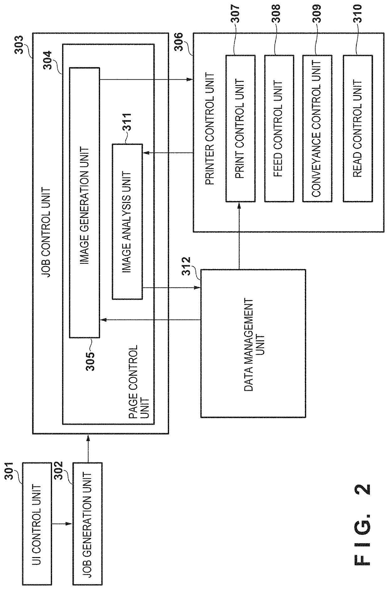
[0081]Case 3 illustrates, as a variation of the present embodiment (cases 1 and 2), an example in which, prior to outputting a sheet on which the chart 500 for tone correction is printed, blank sheets are outputted (in this case, four blank sheets are outputted). In this case, when outputting the blank sheets, the print control unit 307 performs processing for causing a sheet to be outputted from the image output unit 230 without performing image formation. In other words, the image output unit 230 (printer 140) performs a similar operation to the normal print operation so as to output the blank sheets. Accordingly, similarly to case 1, it becomes possible to print the chart 500 for tone correction on the fifth sheet in a state in which the density characteristics of the output image have stabilized.
[0082]Accordingly, it becomes possible to obtain density correction data by reading the chart 500 in a state in which the output image density characteristics stabilized, without wasting...
PUM
 Abstract
Description
Claims
Application Information
 - R&D
- Intellectual Property
- Life Sciences
- Materials
- Tech Scout
- Unparalleled Data Quality
- Higher Quality Content
- 60% Fewer Hallucinations
Browse by: Latest US Patents, China's latest patents, Technical Efficacy Thesaurus, Application Domain, Technology Topic, Popular Technical Reports.
© 2025 PatSnap. All rights reserved.Legal|Privacy policy|Modern Slavery Act Transparency Statement|Sitemap|About US| Contact US: help@patsnap.com


