Medical imaging device

Pending Publication Date: 2022-03-31
BOSTON SCI SCIMED INC
View PDF10 Cites 0 Cited by
  • Summary
  • Abstract
  • Description
  • Claims
  • Application Information

AI Technical Summary

Benefits of technology

The patent describes a medical device with a printed circuit board (PCB) including an imager and a light that are attached to the distal end of the device. The PCB is covered by an optically clear covering that seals the PCB from external environments. The device also includes cables that extend through channels in the shaft and are fixed to the PCB, providing current to the light and imager. The covering also covers all distally-facing surfaces of the PCB. The technical effects of this design include improved image quality and better control of the device's distal portion.

Problems solved by technology

Various components of medical imaging devices are often potted into a distal cap, thereby resulting in overcrowding and interference between said components.
Such issues may cause the imaging devices to malfunction and exhibit various field failures.
For example, plastic optical fibers, which may serve as light sources for imaging devices, may interfere with the cables of the imaging component, thereby resulting in a compromised image feed.
Overcrowding may also cause wear between cables and components, which, in turn, can result in wire corrosion and damage.
Thus, the aforementioned issues and resulting effects may cause significant expense to rework or replace the imaging devices.

Method used


Image

  • Medical imaging device
  • Medical imaging device
  • Medical imaging device

Examples


Embodiment Construction

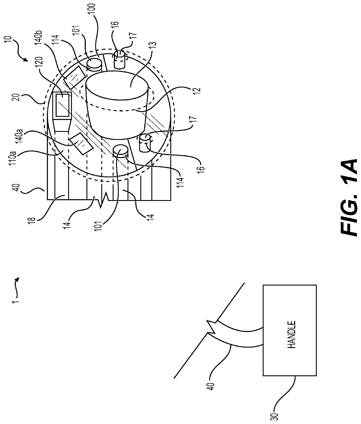
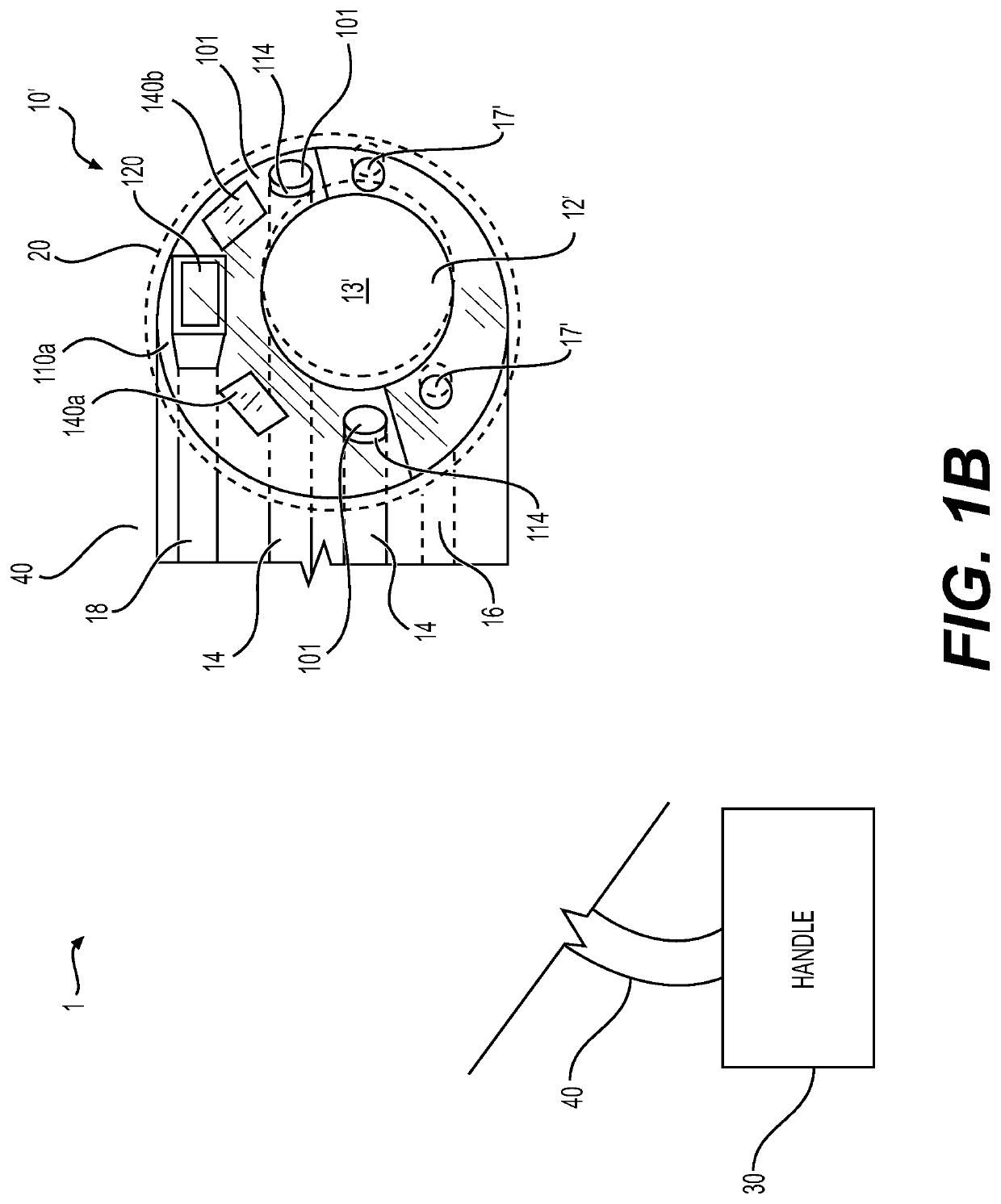
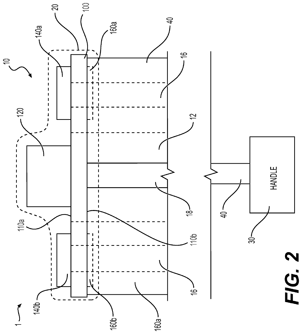
[0019]Reference will now be made in detail to aspects of the disclosure, examples of which are illustrated in the accompanying drawings. Wherever possible, the same or similar reference numbers will be used through the drawings to refer to the same or like parts. The term “distal” refers to a portion farthest away from a user when introducing a device into a subject (e.g., a patient). By contrast, the term “proximal” refers to a portion closest to the user when placing the device into the subject.

[0020]Both the foregoing general description and the following detailed description are exemplary and explanatory only and are not restrictive of the features, as claimed. As used herein, the terms “comprises,”“comprising,”“having,”“including,” or other variations thereof, are intended to cover a non-exclusive inclusion such that a process, method, article, or apparatus that comprises a list of elements does not include only those elements, but may include other elements not expressly liste...


PUM


Abstract

A medical device comprising a shaft defining a first channel having a distal opening, a printed circuit board (PCB) coupled to a distal end of the shaft to expose the distal opening to an external environment, wherein the PCB includes an imager and at least one light, the imager and the at least one light mounted on a distal facing surface of the PCB, and an optically clear covering, wherein the covering covers the imager and the at least one light.

Description

CROSS-REFERENCE TO RELATED APPLICATIONS[0001]This application claims the benefit of priority from U.S. Provisional Application No. 63 / 083,151, filed on Sep. 25, 2020, which is incorporated by reference herein in its entirety.TECHNICAL FIELD[0002]This disclosure relates generally to an imaging device. At least some embodiments of the disclosure relate to a medical imaging device including a printed circuit board (PCB) and an overmold covering a portion of the device.BACKGROUND[0003]Medical procedures often use an imaging device to view internal portions of the body during the procedure. For example, in an endoscopic procedure, an endoscope having lighting and an imager at a distal end may be used to view portions of the gastrointestinal tract during a procedure. Various components of medical imaging devices are often potted into a distal cap, thereby resulting in overcrowding and interference between said components. Such issues may cause the imaging devices to malfunction and exhibi...

Claims


Application Information

Patent Timeline
IPC IPC(8): A61B1/00A61B1/06
CPCA61B1/0008A61B1/0676A61B1/0684A61B1/00117A61B1/05A61B1/0057
Inventor LENT, ERICRAUNIYAR, NIRAJ
Owner BOSTON SCI SCIMED INC
Why Eureka
Try Eureka