
Table for seat

Active Publication Date: 2022-04-07
HONDA MOTOR CO LTD
View PDF23 Cites 2 Cited by
  • Summary
  • Abstract
  • Description
  • Claims
  • Application Information

AI Technical Summary

Benefits of technology

The present invention is a table for a seat in a vehicle that can be moved from a position below the seat to a position above the seat. The table has a top plate and a movable part called the leg part. The leg part can be fixed in place to support the top plate. This invention allows for a convenient and flexible table for seats in vehicles, making it easier for passengers to use.

Problems solved by technology

However, in the apparatus described in JPH10-272972A, since the table body is accommodated in the armrest, the armrest tends to increase in the width direction, and a space limitation for an installation of the seat is large.

Method used


Image

  • Table for seat
  • Table for seat
  • Table for seat

Examples


Embodiment Construction

[0019]Hereinafter, an embodiment of the present invention will be described with reference to FIGS. 1A to 6B. A table for seat according to an embodiment of the present invention is applied to a variety of seats located above a floor of a vehicle, etc. Hereinafter, an example of applying the table for seat to a vehicle seat will be described.

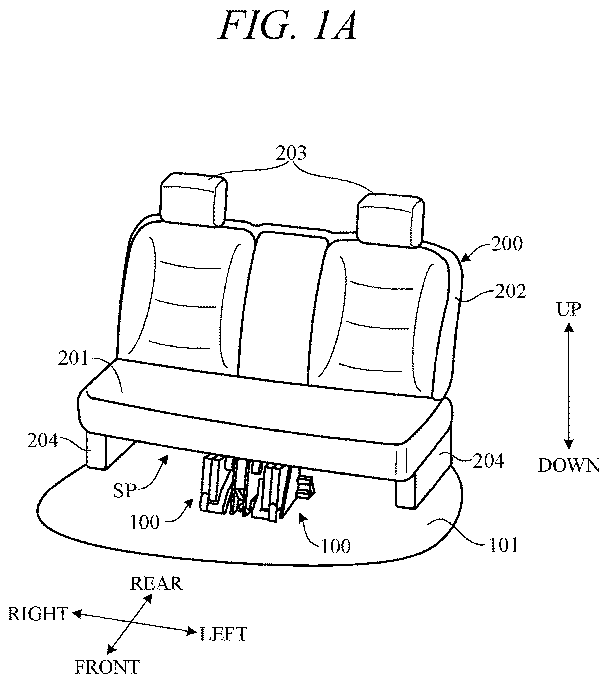
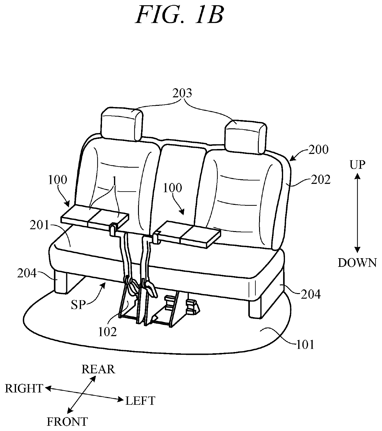
[0020]FIG. 1A and FIG. 1B are perspective views showing an example in which the table for seat 100 according to the embodiment of the present invention is applied to the vehicle. In particular, FIGS. 1A and 1B show an example in which the table for seat 100 is provided in the left and right rear seats of the vehicle. FIG. 1A shows a non-use state of the table for seat 100 in which the table for seat 100 is accommodated in an accommodation position, while FIG. 1B shows a use state of the table for seat 100 in which the table for seat 100 is arranged in a use position. Hereinafter, as shown in the drawing, front-rear direction, left-right directio...


PUM


Abstract

A table for seat provided facing a seat installed above a floor of a vehicle, including a top plate, and a leg part attached to a support portion provided below the seat to movably support the top plate from an accommodation position below the sitting portion to a use position above a sitting portion of the seat. The leg part includes a movable portion, and a fixing device configured to fix a movement of the movable portion in conjunction with an operation of the top plate.

Description

CROSS-REFERENCE TO RELATED APPLICATION[0001]This application is based upon and claims the benefit of priority from Japanese Patent Application No. 2020-169563 filed on Oct. 7, 2020, the content of which is incorporated herein by reference.BACKGROUND OF THE INVENTIONField of the Invention[0002]This invention relates to a table for seat provided at a seat of a vehicle, etc.Description of the Related Art[0003]Conventionally, there has been a known apparatus in which a flat table body is accommodated in an armrest provided on a side of a seat on which an occupant sits. Such an apparatus is described, for example, in Japanese Unexamined Patent Publication No. 10-272972 (JPH10-272972A). In the apparatus described in JPH10-272972A, the table body is supported so as to be housed in the armrest and to be withdrawable from the armrest via a support rod movably supported along a guide formed in the armrest and a bracket fixed to the support rod.[0004]However, in the apparatus described in JPH1...

Claims


Application Information

Patent Timeline
IPC IPC(8): B60N3/00
CPCB60N3/002
Inventor OTSUKI, JUN
Owner HONDA MOTOR CO LTD
Features
  • Generate Ideas
  • Intellectual Property
  • Life Sciences
  • Materials
  • Tech Scout
  • Unparalleled Data Quality
  • Higher Quality Content
  • 60% Fewer Hallucinations
Learn More