Tension sensor

a technology of a pressure sensor and a stent, applied in the direction of instruments, force/torque/work measurement apparatus, measurement devices, etc., can solve the problem that the method, although effective, can be expensiv

Active Publication Date: 2022-04-21
NEMTEK
View PDF2 Cites 0 Cited by
  • Summary
  • Abstract
  • Description
  • Claims
  • Application Information

AI Technical Summary

Benefits of technology

This patent describes a device that detects tension and can maintain electrical contact between two wires when the tension is below a certain level. This device can be used to measure the tension of a wire or a group of wires.

Problems solved by technology

This approach, although effective, can be expensive.

Method used


Image

  • Tension sensor
  • Tension sensor
  • Tension sensor

Examples


Embodiment Construction

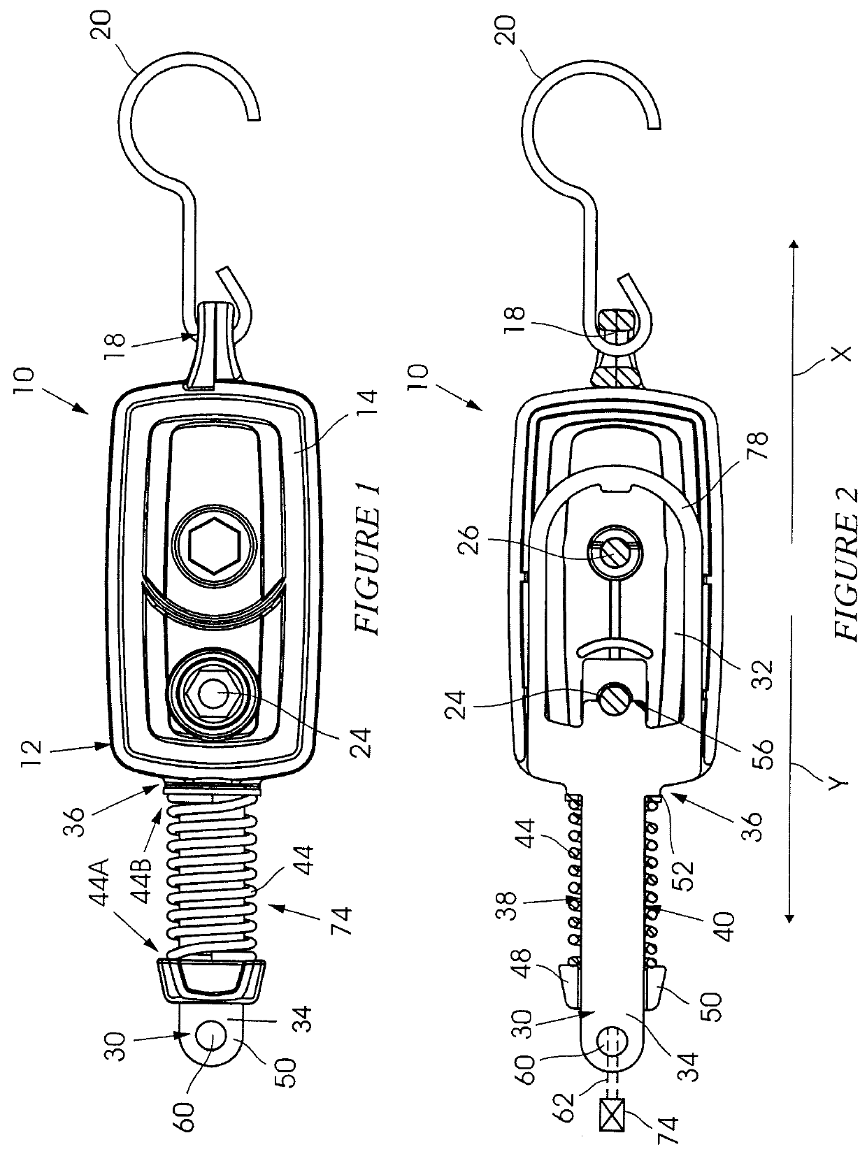
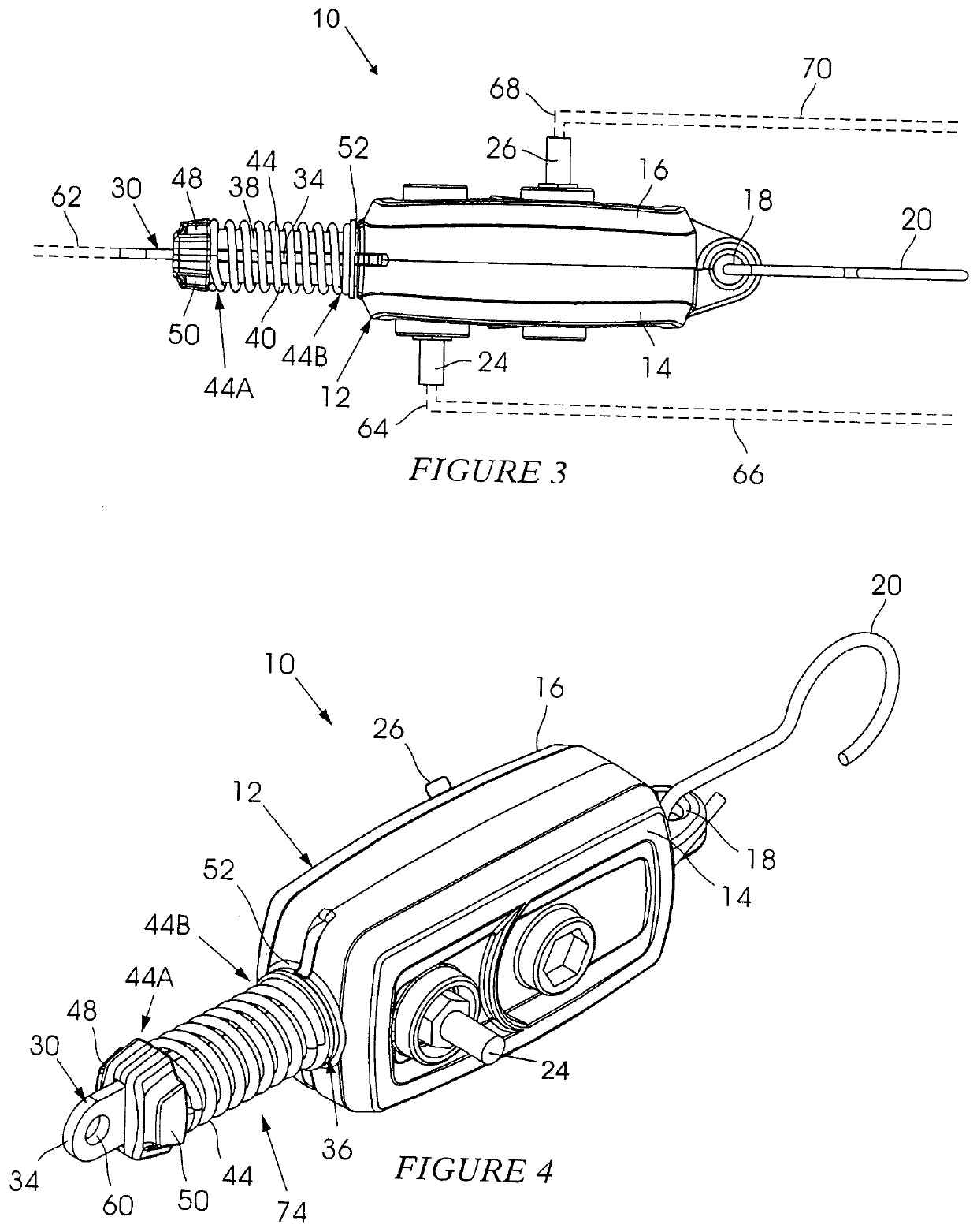
[0034]FIG. 1 and FIG. 3 of the accompanying drawings illustrate in plan and from one side respectively a tension sensor 10 according to one form of the invention. FIG. 4 shows the tension sensor 10 in perspective. FIG. 2 shows the tension sensor 10 with a cover removed.

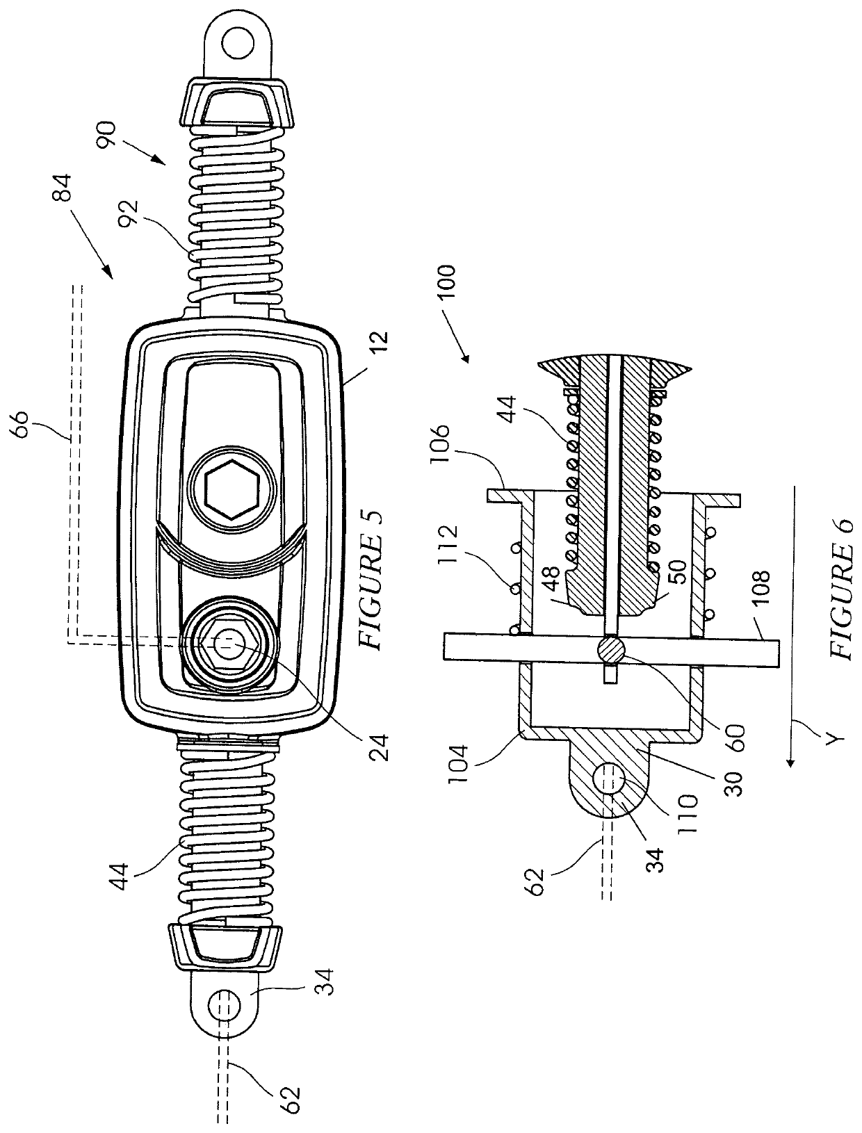
[0035]The tension sensor 10 includes a housing 12 with opposed covers 14 and 16 respectively. An eyelet 18 at one end of the housing 12 and of the covers 14 and 16 is engageable with a hook 20. A first contact 24 extends to one side of the housing 12 through the cover 14. A second contact 26 extends from the housing 12, in an opposing direction to the contact 24, through the cover 16. A conductive member 30 is partly positioned in and projects from the housing 12. The conductive member 30 has a loop 32 which is located inside the housing 12 between the covers 14 and 16, and an arm 34 which projects through an opening 36 from the housing 12. Two spaced apart limbs 38 and 40 respectively extend from the housing 12 and t...


PUM

PropertyMeasurementUnit
voltageaaaaaaaaaa
tensionaaaaaaaaaa
electrically conductiveaaaaaaaaaa

Abstract

A tension sensor for an electrified fence which includes two contacts and a spring arrangement which, in response to a tension level in a taut wire in the electrified fence keeps the contacts electrically connected to each other when the tension level is below a predetermined value and which breaks such electrical connectivity when the tension level exceeds the predetermined value.

Description

BACKGROUND OF THE INVENTION[0001]This invention relates to a tension sensor which is responsive to a level of tension in a taut wire, for example in an electrified fence.[0002]An electrified fence can be implemented in various ways. In one configuration earth and live wires, respectively arranged in series loops, are mounted in alternating fashion to supports. If a live wire touches an earth wire a short circuit occurs. Similarly, if a live wire or an earth wire is severed then an open circuit arises. In each instance detection of the event is achieved by means of an energizer which continuously imparts pulses to the wires and which is also used to monitor the wires for an open circuit, or a short circuit, condition.[0003]An electrified fence can however be penetrated if an intruder is able to part adjacent earth and live wires sufficiently to form a gap which is large enough for the intruder to pass through. Normally this is done at ground level and a lowermost wire, which is usual...

Claims


Application Information

Patent Timeline
Patent Type & Authority Applications(United States)
IPC IPC(8): G01L5/103
CPCG01L5/103H01H35/006H01H17/28
Inventor MANIOUDAKIS, NICOLAS
Owner NEMTEK
Why Eureka
Try Eureka