Rotatable X shaped Folding Flip Grip

a flip grip and x-shaped technology, applied in the direction of machine supports, telephone set constructions, stand/trestles, etc., can solve the problems of rigid attachment of current devices such as pop sockets, and limit the kinds of movements and operations that they allow, so as to enhance security and comfort

Pending Publication Date: 2022-04-28
SNOW RILEY DAVID
View PDF0 Cites 0 Cited by
  • Summary
  • Abstract
  • Description
  • Claims
  • Application Information

AI Technical Summary

Benefits of technology

[0008]The flipgrip device has enhance...

Problems solved by technology

Current devices such as pop sockets are rigidly attached to the rear of the...

Method used


Image

  • Rotatable X shaped Folding Flip Grip
  • Rotatable X shaped Folding Flip Grip
  • Rotatable X shaped Folding Flip Grip

Examples


Embodiment Construction

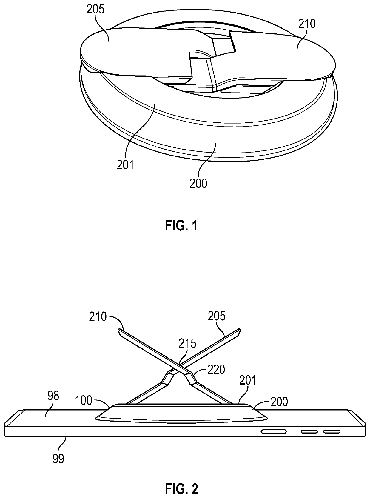
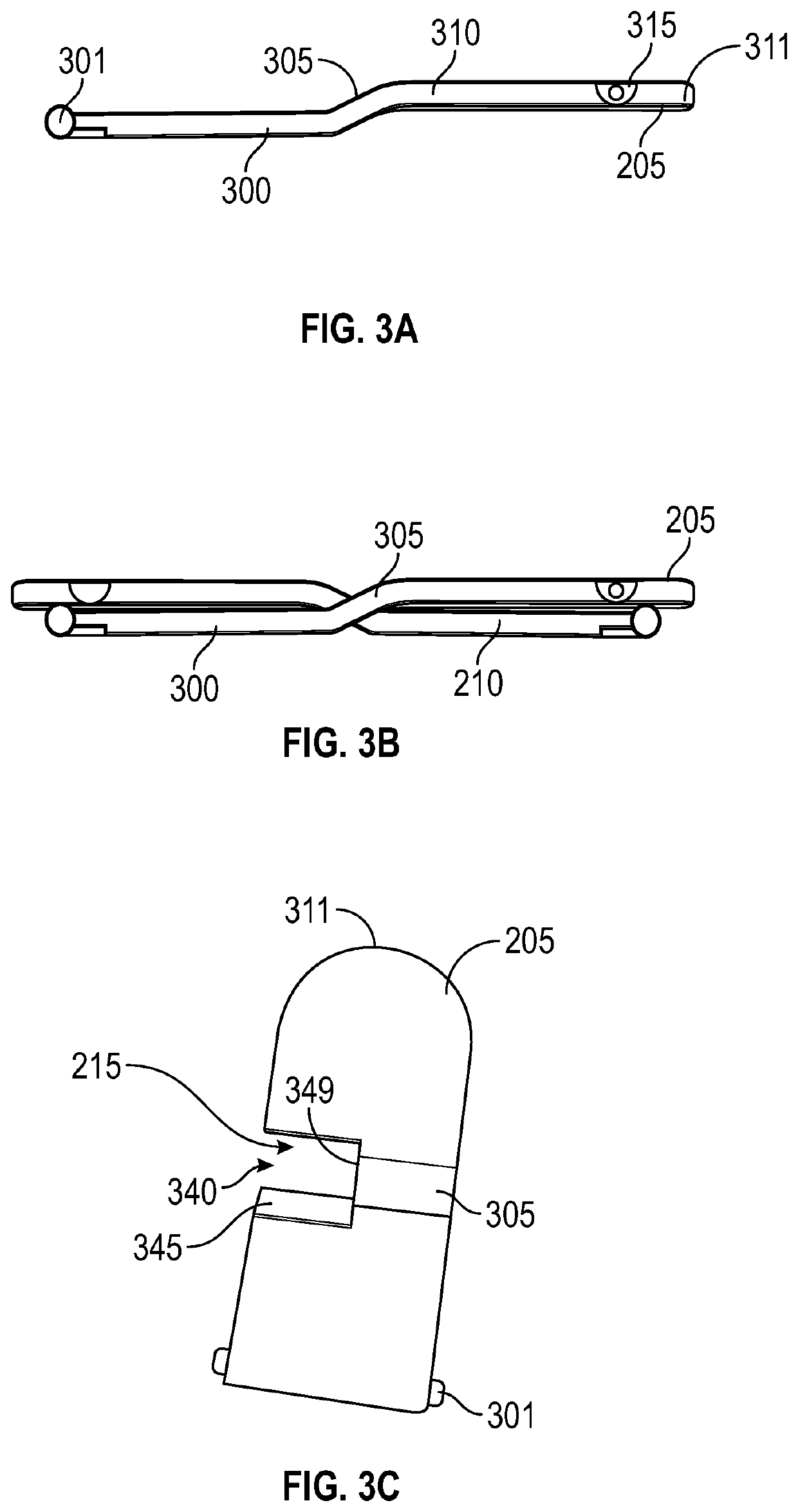
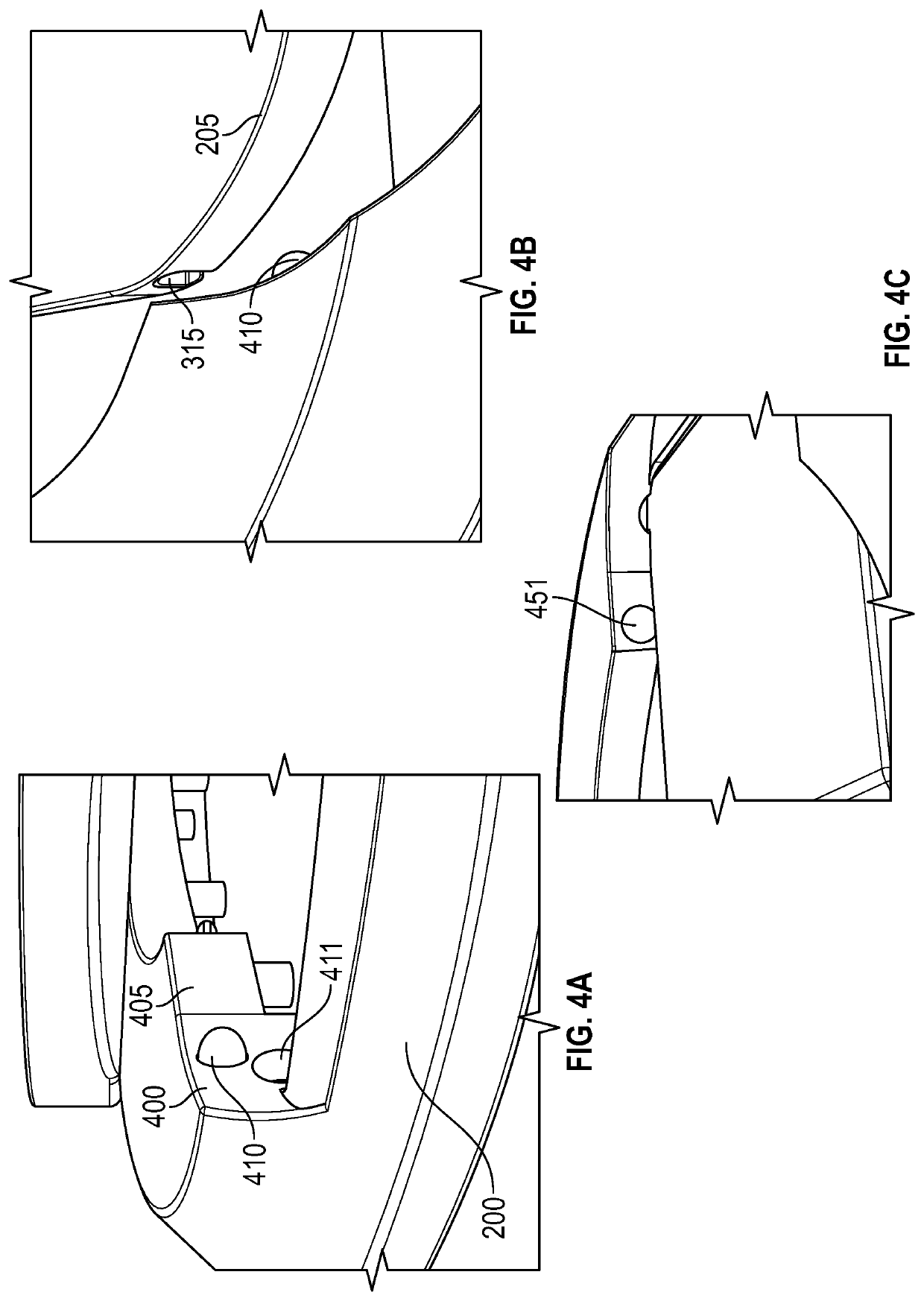
[0025]The present application describes a “flipgrip” device that attaches to the rear of a portable phone, and allows more easy holding of the phone. The flipgrip device is removable, foldable, and rotatable. The flipgrip device is folded to a flat position where it lays flat against the back of the mobile phone. A ring adheres to the rear of the phone, and the base snaps on to the ring. The base has legs that are unfolded to form an X shaped grip device, which has multiple surfaces enabling holding of the phone with a user's hands or fingers.

[0026]FIGS. 1 and 2 respectively show the flipgrip device in its folded and unfolded state respectively.

[0027]FIG. 2 shows the structure of the flipgrip device, and its configuration when unfolded. The flipgrip device 100 is formed of a round base 200 that attaches to the rear surface 98 of the portable phone 99. A first leg 205 attaches to and hinges relative to a first location on the base 200. A second leg 210 attaches to and hinges relative...


PUM


Abstract

A flipgrip system for a phone. The flipgrip includes two hinging legs that unfold into an X shape, and fold flat. A ring adheres to the rear of the phone and a base can snap onto the ring. The base can spin relative to the ring and also be removed from the back of the phone. The first and second legs hinge relative to the base, out into the X shaped position, or in to the folded flat position.

Description

[0001]This application claims priority to provisional application No. 63 / 198,506, filed Oct. 23, 2020, the entire contents of which are herewith incorporated by reference.BACKGROUND[0002]Devices are used to allow a user to hold onto a phone in a different way. A typical phone grip, like a pop socket, often attaches to the rear of the phone, and allows holding the phone from the rear.SUMMARY OF THE INVENTION[0003]The inventor recognized a number of drawbacks with the current systems and has conceived of and describes herein, an improved design.[0004]Current devices such as pop sockets are rigidly attached to the rear of the phone, and are limited in the kinds of movements and operations that they allow.[0005]The present application describes a foldable “x-shaped” phone grip device, called a flipgrip, that attaches to a rear surface of a mobile phone (or other similar device). The flipgrip device has a ring that attaches to the rear of the phone, and a base attaches to the ring. The b...

Claims


Application Information

Patent Timeline
IPC IPC(8): F16M13/04F16M13/06
CPCF16M13/04F16M13/06F16M11/105F16M11/2021H04M1/04
Inventor SNOW, RILEY DAVID
Owner SNOW RILEY DAVID
Why Eureka
Try Eureka