
Image forming device

Pending Publication Date: 2022-05-19
KONICA MINOLTA INC
View PDF1 Cites 0 Cited by
  • Summary
  • Abstract
  • Description
  • Claims
  • Application Information

AI Technical Summary

Benefits of technology

The technical problem addressed in this patent is to create an image forming device that can reduce unnecessary toner consumption caused by edge effects, while maintaining image quality regardless of changes in the causes or degrees of influence of the edge effects.

Problems solved by technology

When the edge effect occurs, more toner is consumed than necessary, and line width of line drawings and characters varies, causing deterioration of image quality.
Further, small sized characters may be rendered illegible if density is too high, and there is a risk of illegibility just from an increase in toner amount due to the edge effect.
As described above, the degree of influence of the edge effect varies depending on the distance Ds from the outer circumferential surface of the developer roller to the outer circumferential surface of the photosensitive drum, and therefore if pixel gradation is uniformly corrected according to only distance from edges without regard to the distance Ds, a decrease in image quality cannot be sufficiently prevented.
On the other hand, if toner adhesion amount is uniformly corrected according to the distance Ds without regard to distance from edges, a decrease in image quality cannot be sufficiently prevented.
Further, if only density of single pixel width line images is stabilized, then it is not possible to manage variation in influence of the edge effect according to distance from edges.
Further, when small sized characters are made illegible due to the edge effect, an amount of toner adhering varies depending on variation of influence of the edge effect, and therefore even if laser beam power is adjusted according to character size, legibility of illegible characters cannot be sufficiently improved.
Thus, even if image correction is performed focusing only on one condition, deterioration of image quality due to the edge effect cannot be sufficiently suppressed.

Method used


Image

  • Image forming device
  • Image forming device
  • Image forming device

Examples


Embodiment Construction

[0026]Hereinafter, one or more embodiments of the present invention will be described with reference to the drawings. However, the scope of the invention is not limited to the disclosed embodiments.

[1] Structure of Image Forming Device

[0027]First, structure of an image forming device pertaining to an embodiment is described below.

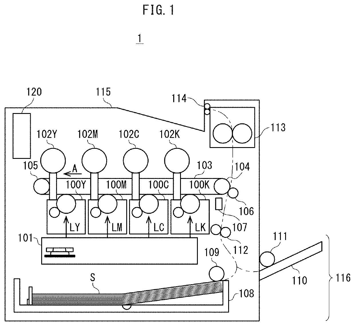
[0028]As illustrated in FIG. 1, an image forming device 1 is a tandem-type color printer that includes imaging units 100Y, 100M, 100C, and 100K that form toner images in yellow (Y), magenta (M), cyan (C), and black (K) colors, respectively. Toner cartridges 102Y, 102M, 102C, and 102K each containing a developer including a corresponding color of toner are detachably attached to the image forming device 1.

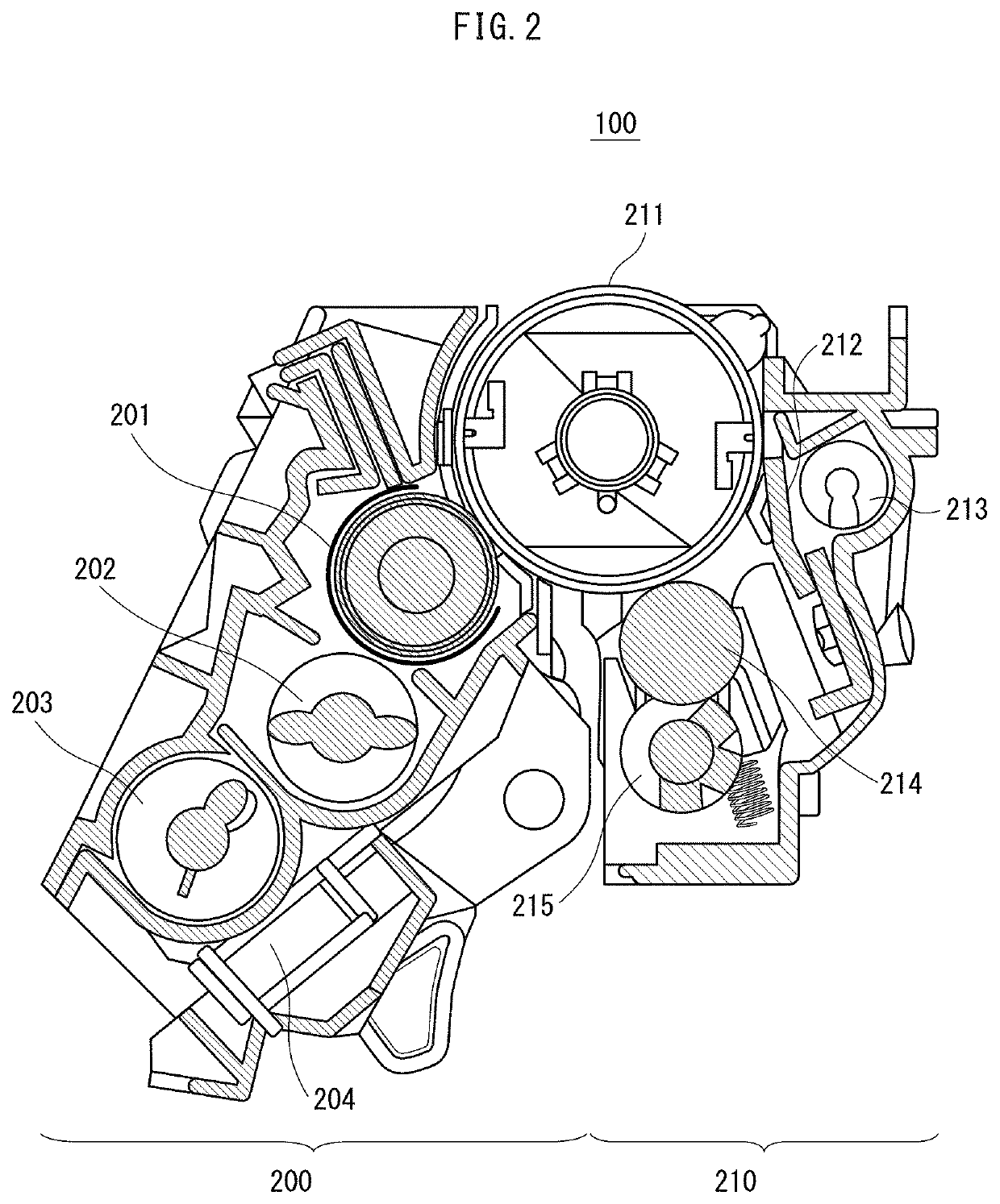
[0029]The imaging units 100Y, 100M, 100C, and 100K each receive supply of two-component developer from a corresponding one of the toner cartridges 102Y, 102M, 102C, 102K to form a toner image. The imaging units 100Y, 100M, 100C, and 100K have a common struc...


PUM


Abstract

An image forming device including a forming unit, an adhesion amount detector, a correction coefficient determiner, and a correction unit. The forming unit forms line images each having a different line width. The adhesion amount detector detects a toner adhesion amount for each of the line images. The correction coefficient determiner determines, according to the toner adhesion amounts detected for each line width, correction coefficients for a gradation value of the line images of each line width. The correction unit corrects a gradation value of a line image using a correction coefficient corresponding to the line width of the line image when forming the line image.

Description

CROSS REFERENCE TO RELATED APPLICATIONS[0001]The present invention claims priority under 35 U.S.C. § 119 to Japanese Patent Application No. 2020-191328, filed on Nov. 18, 2020, the entire content of which is incorporated herein by reference.BACKGROUND(1) Technical Field[0002]The present disclosure relates to image forming devices, and in particular to techniques for suppressing an increase in toner consumption and a decrease in image quality due to an edge effect.(2) Description of the Related Art[0003]Conventionally, an electrophotographic image forming device forms a toner image by electrostatically adsorbing toner on an electrostatic latent image formed on a photosensitive surface. Taking the case of using negatively charged toner as an example, an electrostatic latent image has an image area to which toner is attached by development and a non-image area to which toner is not attached. More toner attaching to an area of the image area close the edge of the non-image area than dis...

Claims


Application Information

Patent Timeline
IPC IPC(8): G03G15/00G03G15/01
CPCG03G15/5041G03G15/5062G03G15/556G03G15/0131G03G15/5087
Inventor NAKANO, MUNENORIHIROTA, SOHTSUTSUMI, YOSHINORI
Owner KONICA MINOLTA INC
Features
  • Generate Ideas
  • Intellectual Property
  • Life Sciences
  • Materials
  • Tech Scout
  • Unparalleled Data Quality
  • Higher Quality Content
  • 60% Fewer Hallucinations
Learn More