Control apparatus, control method, and non-transitory computer-readable storage medium

Pending Publication Date: 2022-05-19
CANON KK
View PDF24 Cites 0 Cited by
  • Summary
  • Abstract
  • Description
  • Claims
  • Application Information

AI Technical Summary

Benefits of technology

The present invention provides a way to stop an image capturing device from executing certain functions when it is not the control target. This is helpful in preventing unwanted actions from being performed by the image capturing device.

Problems solved by technology

In the above-described application, when a camera is removed from being a control target in a state where a control stop command is not transmitted after the start command of a specific function is transmitted, there is a problem that the command for stopping the specific function will not be transmitted to the camera and the limit of the movable range of the function will be reached.

Method used


Image

  • Control apparatus, control method, and non-transitory computer-readable storage medium
  • Control apparatus, control method, and non-transitory computer-readable storage medium
  • Control apparatus, control method, and non-transitory computer-readable storage medium

Examples


first embodiment

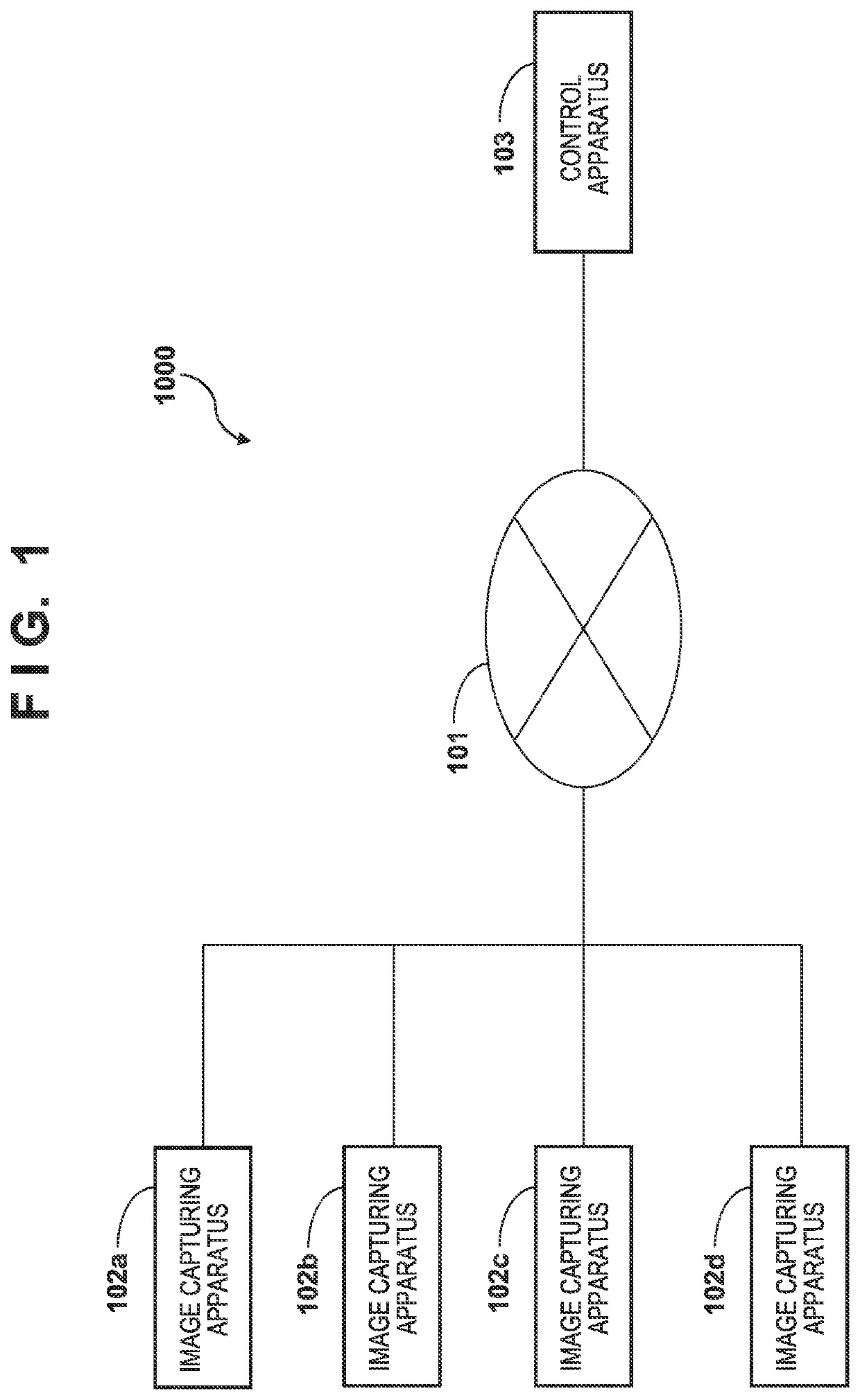
[0021]An example of a configuration of a camera system 1000 according to the present embodiment is described with reference to FIG. 1. As shown in FIG. 1, the camera system 1000 includes a plurality of image capturing apparatuses (image capturing apparatus 102a, image capturing apparatus 102b, image capturing apparatus 102c, image capturing apparatus 102d) and a control apparatus 103, and the plurality of image capturing apparatuses and the control apparatus 103 are connected to a network 101.

[0022]First, the network 101 is described. The network 101 includes, for example, a plurality of routers, switches, cables, and the like that conform to the communication standard of Ethernet®. Note that, for the network 101, as long as data communication can be performed between the plurality of image capturing apparatuses and the control apparatus 103, the communication standard, scale, and configuration is not limited to a specific communication standard, a specific scale, or a specific conf...

second embodiment

Variation of Second Embodiment

[0099]In the following, differences from the second embodiment are described, and unless specifically mentioned below, it is assumed the present embodiment is the same as the second embodiment. In the second embodiment, a case where a specific function is stopped in accordance with the operation state of the image capturing apparatus when the image capturing apparatus is removed from the control target has been described. In the present variation, if a specific function is in operation in the image capturing apparatus and an automatic control function of the image capturing apparatus is not operating when removing the image capturing apparatus from the control target, a command for stopping the operation of the specific function is transmitted to the image capturing apparatus. Note that, preset, preset cycle, trace, and the like are given as automatic control functions of the image capturing apparatus.

[0100]Next, a process that the control apparatus 103...


PUM


Abstract

A control apparatus comprises a determination unit configured to, in a case where a user operation for removing an image capturing apparatus being a control target from the control target is performed, determine whether or not the image capturing apparatus is executing a specific function, and a control unit configured to, in a case where the determination unit determines that the image capturing apparatus is executing the specific function, cause the image capturing apparatus to stop the specific function.

Description

BACKGROUND OF THE INVENTIONField of the Invention[0001]The present invention relates to a technique for controlling an image capturing apparatus.Description of the Related Art[0002]Currently, in the video production market, systems for remotely controlling a plurality of remote cameras (hereinafter simply referred to as “cameras”) connected to a network so that fewer cameramen can control a plurality of cameras are increasing. In such systems, an application capable of changing the settings of each camera and controlling PTZ (pan / tilt / zoom) while displaying images of a plurality of cameras is used. The control of the PTZ, the control of the focus, and the like can also be simultaneously controlled for a plurality of cameras. In such an application, it is possible to select whether or not to set each camera as a control target due to the feature that it can be connected to a plurality of cameras. The invention disclosed in Japanese Patent No. 3996960 proposes a camera control system ...

Claims


Application Information

Patent Timeline
IPC IPC(8): H04N5/232
CPCH04N5/23225H04N5/23299H04N5/23216H04N5/23206H04N7/181H04N23/661H04N23/617H04N23/62H04N23/69H04N23/695
Inventor MIZUMA, KENSHIRO
Owner CANON KK
Why Eureka
Try Eureka