Culture monitoring system, control method, and computer-readable medium
a monitoring system and control method technology, applied in the field of culture monitoring system, can solve the problems of affecting the growth of biological samples, reducing the temperature of biological samples,
- Summary
- Abstract
- Description
- Claims
- Application Information
AI Technical Summary
Benefits of technology
Problems solved by technology
Method used
Image
Examples
first embodiment
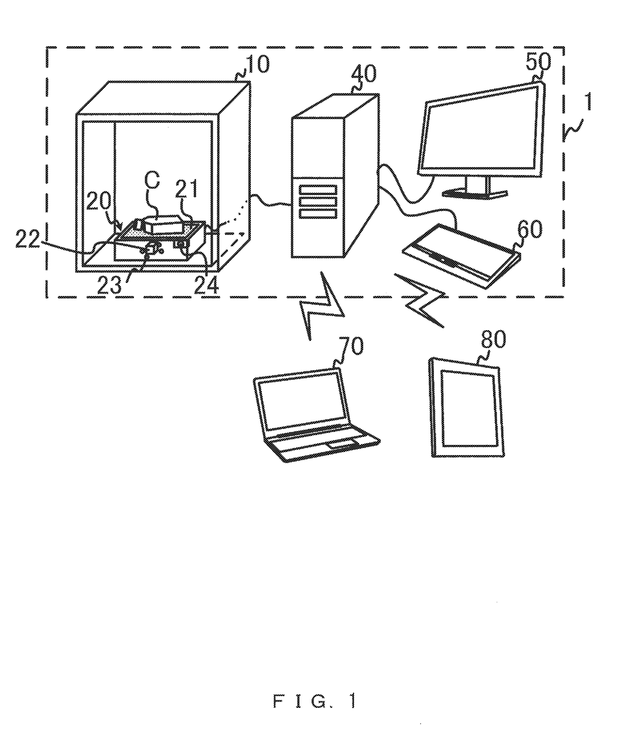
[0068]FIG. 7 is a flowchart that illustrates an example of monitoring processing according to the present embodiment. The monitoring processing illustrated in FIG. 7 is performed by the controller 40, and indicates a method for controlling the image acquisition device 20 arranged in the incubator 10. FIG. 8 is a sequence diagram that illustrates a communication of data between the controller 40 and the image acquisition device 20. FIG. 9 illustrates an image acquisition point according to the present embodiment. FIG. 10 illustrates an example of a change in a state of the image acquisition device 20 according to the present embodiment. FIG. 11 illustrates a screen displayed in a stopping state.
[0069]The culture monitoring system 1 according to the first embodiment is described below with reference to FIGS. 7 to 11 using, as an example, monitoring processing of monitoring a biological sample by performing time-lapse photography.
[0070]In the present embodiment, the estimator 48 estima...
second embodiment
[0085]FIG. 13 is a flowchart that illustrates an example of monitoring processing according to the present embodiment. FIG. 14 illustrates an image acquisition point according to the present embodiment.
[0086]The culture monitoring system 1 according to the second embodiment is described below with reference to FIGS. 13 and 14 using, as an example, the monitoring processing of monitoring a biological sample by performing time-lapse photography. The present embodiment is different from the first embodiment in that, instead of the flask C, a multi-well plate C1 is used as a culture vessel, and in that a biological sample is accommodated in each of a plurality of wells W formed on the multi-well plate C1, as illustrated in FIG. 14. It is also different from the first embodiment in that monitoring processing illustrated in FIG. 13 is performed instead of the monitoring processing illustrated in FIG. 7.
[0087]In the present embodiment, a plurality of biological samples accommodated in a pl...
third embodiment
[0099]FIG. 15 is a flowchart that illustrates preparation processing according to the present embodiment. FIG. 16 illustrates an example of a change in a state of the image acquisition device 20 according to the present embodiment.
[0100]The culture monitoring system 1 according to the third embodiment is described below with reference to FIGS. 15 and 16 using, as an example, the preparation processing in which a user manipulates the image acquisition device 20 manually before monitoring processing is started. The preparation processing is performed in order to, for example, adjust a condition for acquiring an image or specify a plurality of image acquisition points. Here, the image acquisition device 20 performs various operations for an image acquisition according to an arbitrary manual manipulation performed by a user.
[0101]In the present embodiment, during a preparation period in which the preparation processing is performed, the estimator 48 determines, on the basis of a control...
PUM
| Property | Measurement | Unit |
|---|---|---|
| temperature | aaaaa | aaaaa |
| temperature | aaaaa | aaaaa |
| stopping time | aaaaa | aaaaa |
Abstract
Description
Claims
Application Information
 - R&D
- Intellectual Property
- Life Sciences
- Materials
- Tech Scout
- Unparalleled Data Quality
- Higher Quality Content
- 60% Fewer Hallucinations
Browse by: Latest US Patents, China's latest patents, Technical Efficacy Thesaurus, Application Domain, Technology Topic, Popular Technical Reports.
© 2025 PatSnap. All rights reserved.Legal|Privacy policy|Modern Slavery Act Transparency Statement|Sitemap|About US| Contact US: help@patsnap.com


