Equipment condition-based corrosion life monitoring system and method

a technology of condition-based corrosion life monitoring and equipment, which is applied in the direction of testing/monitoring control systems, process and machine control, instruments, etc., can solve the problems of equipment failure, equipment that includes metal components can corrode over time, and equipment failur

Active Publication Date: 2018-12-13
GENERAL ELECTRIC CO
View PDF1 Cites 3 Cited by
  • Summary
  • Abstract
  • Description
  • Claims
  • Application Information

AI Technical Summary

Benefits of technology

[0003]In one embodiment, a system includes an analysis controller configured to determine multi-dimensional characteristics of one or more corrosion pits in equipment and to determine one or more stresses on the equipment based on the characteristics of the corrosion that are determined. The analysis controller also is configured to generate a control signal to implement one or more remedial actions to one or more of remove the one or more corrosion pits, repair the equipment, or restrict operation of the equipment based on the one or more stresses that are determined.
[0004]In one embodiment, a method includes optically determining multi-dimensional characteristics of one or more corrosion pits in equipment, determining one or more stresses on the equipment based on the multi-dimensional characteristics of the one or more corrosion pits that are determined, and implementing one or more remedial actions to one or more of remove the one or more corrosion pits, repair the equipment, or restrict operation of the equipment based on the one or more stresses that are determined.

Problems solved by technology

Equipment that includes metal components can corrode over time.
The corrosion can develop pitting in the equipment, which eventually can lead to cracks in the equipment and eventual failure of the equipment.
But, this periodic inspection of corrosion may only examine the propagation of cracks and / or may only measure a single corrosion pit, and not examine other aspect of corrosion.
As a result, predictions of how much longer the equipment can continue to safely operate (e.g., the remaining useful service life of the equipment) may be inaccurate.

Method used


Image

  • Equipment condition-based corrosion life monitoring system and method
  • Equipment condition-based corrosion life monitoring system and method
  • Equipment condition-based corrosion life monitoring system and method

Examples


Embodiment Construction

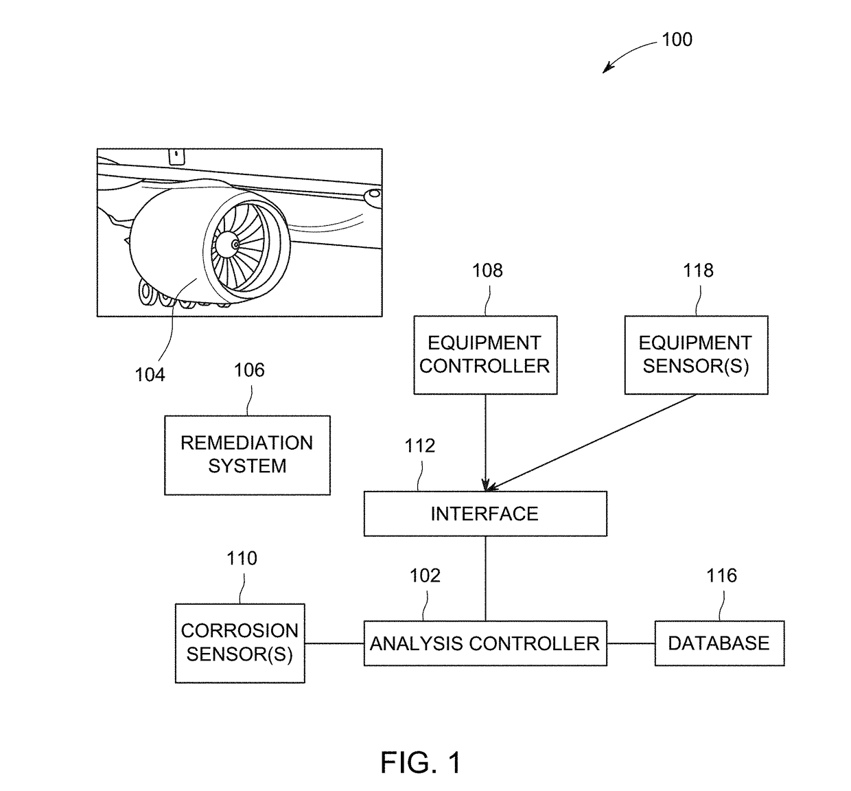
[0012]One or more embodiments of the inventive subject matter described herein provide systems and methods that monitor corrosion of equipment and, based on the corrosion that is monitored, determine a predicted remaining useful service life of the equipment. While the description herein focuses on predicting the remaining useful service life of engine turbines, the systems and methods can be used to predict the remaining useful service life of other types of equipment, such as other vehicle components, bridges, rails, or the like. The prediction of the remaining useful service life of equipment can be referred to as lifing the equipment. The predicted remaining useful service life can represent an amount of time that the system or method predict that the equipment can continue to be operational before failing or otherwise being unable to function.

[0013]The systems and methods can apply an analytic based equipment corrosion life monitor in conjunction with optical measurements of co...


PUM

PropertyMeasurementUnit
aspect ratioaaaaaaaaaa

Abstract

An analysis controller determines multi-dimensional characteristics of one or more corrosion pits in equipment. These characteristics can include depths, widths, and/or aspect ratios of the corrosion pits. The controller also determines one or more stresses on the equipment based on the characteristics of the corrosion that are determined. The analysis controller also generates a control signal to implement one or more remedial actions to one or more of remove the one or more corrosion pits, repair the equipment, or restrict operation of the equipment based on the one or more stresses that are determined.

Description

FIELD[0001]The subject matter described herein relates to monitoring corrosion of equipment, such as turbine engines or other equipment.BACKGROUND[0002]Equipment that includes metal components can corrode over time. The corrosion can develop pitting in the equipment, which eventually can lead to cracks in the equipment and eventual failure of the equipment. Equipment may be scheduled for periodic inspection to check on the existence and / or progression of corrosion. But, this periodic inspection of corrosion may only examine the propagation of cracks and / or may only measure a single corrosion pit, and not examine other aspect of corrosion. As a result, predictions of how much longer the equipment can continue to safely operate (e.g., the remaining useful service life of the equipment) may be inaccurate.BRIEF DESCRIPTION[0003]In one embodiment, a system includes an analysis controller configured to determine multi-dimensional characteristics of one or more corrosion pits in equipment ...

Claims


Application Information

Patent Timeline
Patent Type & Authority Applications(United States)
IPC IPC(8): G01N17/04G01B21/16G01B11/02
CPCG01N17/04G01M15/14G01B11/02G01B21/16G01N17/00G01N17/006G05B23/0283
Inventor DETOR, ANDREW JOSEPHBEWLAY, BERNARD PATRICKSOARE, MONICA
Owner GENERAL ELECTRIC CO
Why Eureka
Try Eureka