Power supply apparatus and image forming apparatus

Active Publication Date: 2022-05-26
CANON KK
View PDF2 Cites 0 Cited by
  • Summary
  • Abstract
  • Description
  • Claims
  • Application Information

AI Technical Summary

Benefits of technology

[0006]The present disclosure is directed to suppressing an electrolytic solution jetted out of an elec

Problems solved by technology

More specifically, the adherence of the electrolytic solution to the primary circuitry may cause a short circuit, resulting in flow of a large current.
As a result, the space for providing the deflection plate discussed in Japanese Patent No. 6598511 cannot be secured, and the jetted electrolytic solution may be reflected on the ext

Method used


Image

  • Power supply apparatus and image forming apparatus
  • Power supply apparatus and image forming apparatus
  • Power supply apparatus and image forming apparatus

Examples


Embodiment Construction

[Configuration of Image Forming Apparatus]

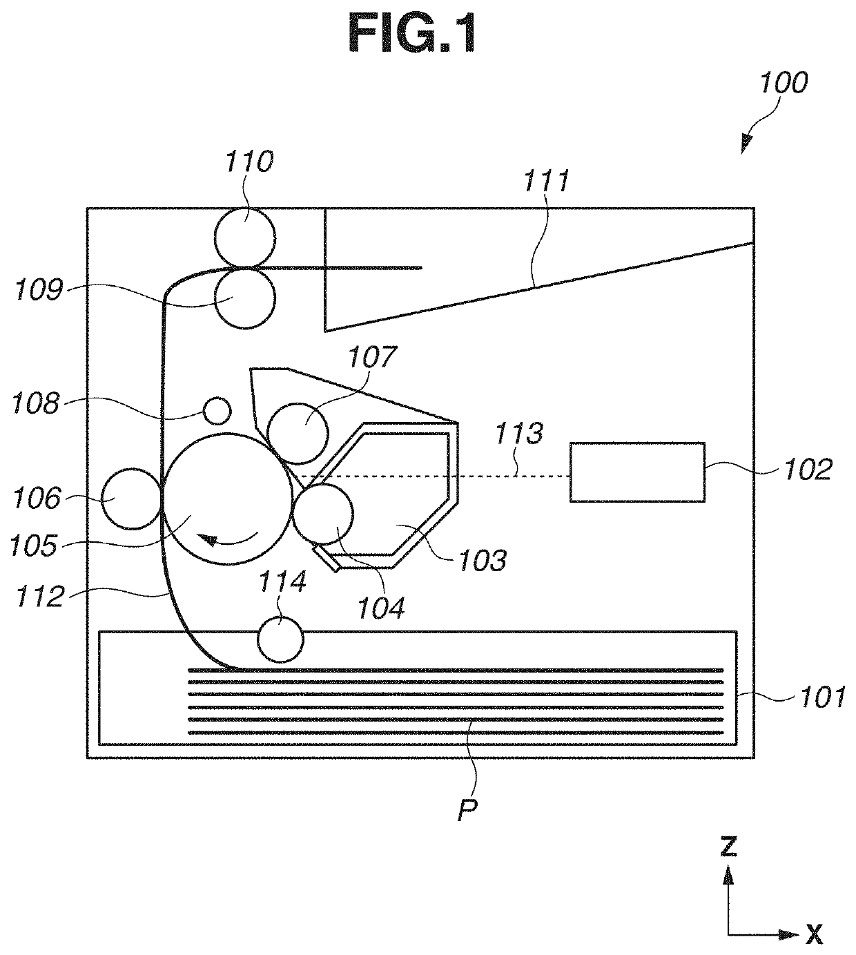
[0017]A configuration of an image forming apparatus 100 according to an exemplary embodiment of the present disclosure will be described. The image forming apparatus 100 according to the present exemplary embodiment is a monochrome laser printer using an electrophotographic process, and is configured to form an image on paper P as a recording material by using toner (developer), based on image information transmitted from an external apparatus such as a personal computer.

[0018]In the following description, a height direction (opposite to a gravity direction) of the image forming apparatus 100 placed on a horizontal surface will be referred to as a Z direction. A direction crossing the Z direction and parallel to an axial direction (a main scanning direction) of a photosensitive drum 105 to be described below will be referred to as a Y direction. A direction crossing the Y direction and the Z direction will be referred to as an X direction. I...


PUM


Abstract

A power supply apparatus includes a transformer, an electrolytic capacitor provided in primary circuitry of the transformer, a board, and a heat sink having a protruding portion and a cover portion. The electrolytic capacitor includes an explosion-proof valve that opens to cause an electrolytic solution to be jetted from the electrolytic capacitor. The electrolytic capacitor is placed on the board so that a surface of the electrolytic capacitor opposite to a surface on which the explosion-proof valve is provided faces the board. The cover portion has a hole formed in the cover portion and, when the cover portion is viewed in a direction vertical to the surface of the electrolytic capacitor on which the explosion-proof valve is provided, at least the explosion-proof valve and the hole formed in the cover portion do not overlap each other and the cover portion encompasses the explosion-proof valve.

Description

BACKGROUNDField[0001]The present disclosure relates to a power supply apparatus including an electrolytic capacitor having an explosion-proof valve, and an image forming apparatus including the power supply apparatus.Description of the Related Art[0002]Conventional image forming apparatuses such as laser printers use a power supply apparatus that rectifies and smooths an alternating current from a commercial power source and converts the current into a direct current. In a switching power supply apparatus that is a kind of direct current power supply apparatus, a rectified and smoothed direct current is input into a transformer and switched to obtain a desired output. Examples of the switching power supply apparatus include those using methods such as a flyback method, a forward method, and a current resonance method. These switching power supply apparatuses include a rectifier circuit that rectifies an input alternating current, and a smoothing circuit that smooths the rectified cu...

Claims


Application Information

Patent Timeline
IPC IPC(8): H01F27/40H01F27/28H01F27/08H01F27/02G03G15/00G03G21/20
CPCH01F27/40H01F27/28G03G21/20H01F27/02G03G15/80H01F27/08H02M3/33507H02M3/003
Inventor HIRABAYASHI, JUN
Owner CANON KK
Why Eureka
Try Eureka