Input device and movable object

Pending Publication Date: 2022-05-26
PANASONIC INTELLECTUAL PROPERTY MANAGEMENT CO LTD
View PDF0 Cites 0 Cited by
  • Summary
  • Abstract
  • Description
  • Claims
  • Application Information

AI Technical Summary

Benefits of technology

[0005]It is an object of the present disclosure to provide an input devi

Problems solved by technology

This may complicate the structur

Method used


Image

  • Input device and movable object
  • Input device and movable object
  • Input device and movable object

Examples


embodiment

[0024](1) Overview

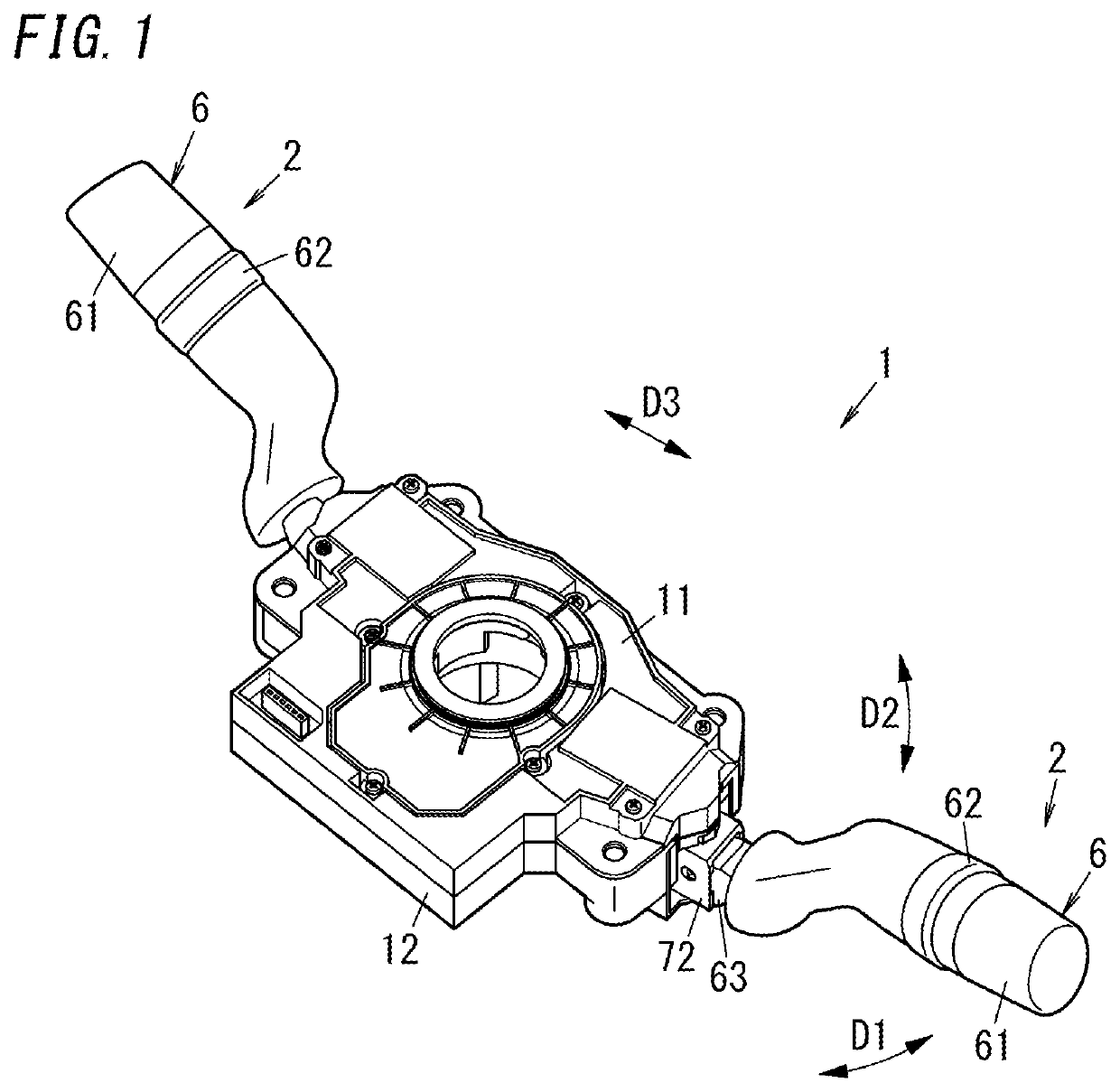
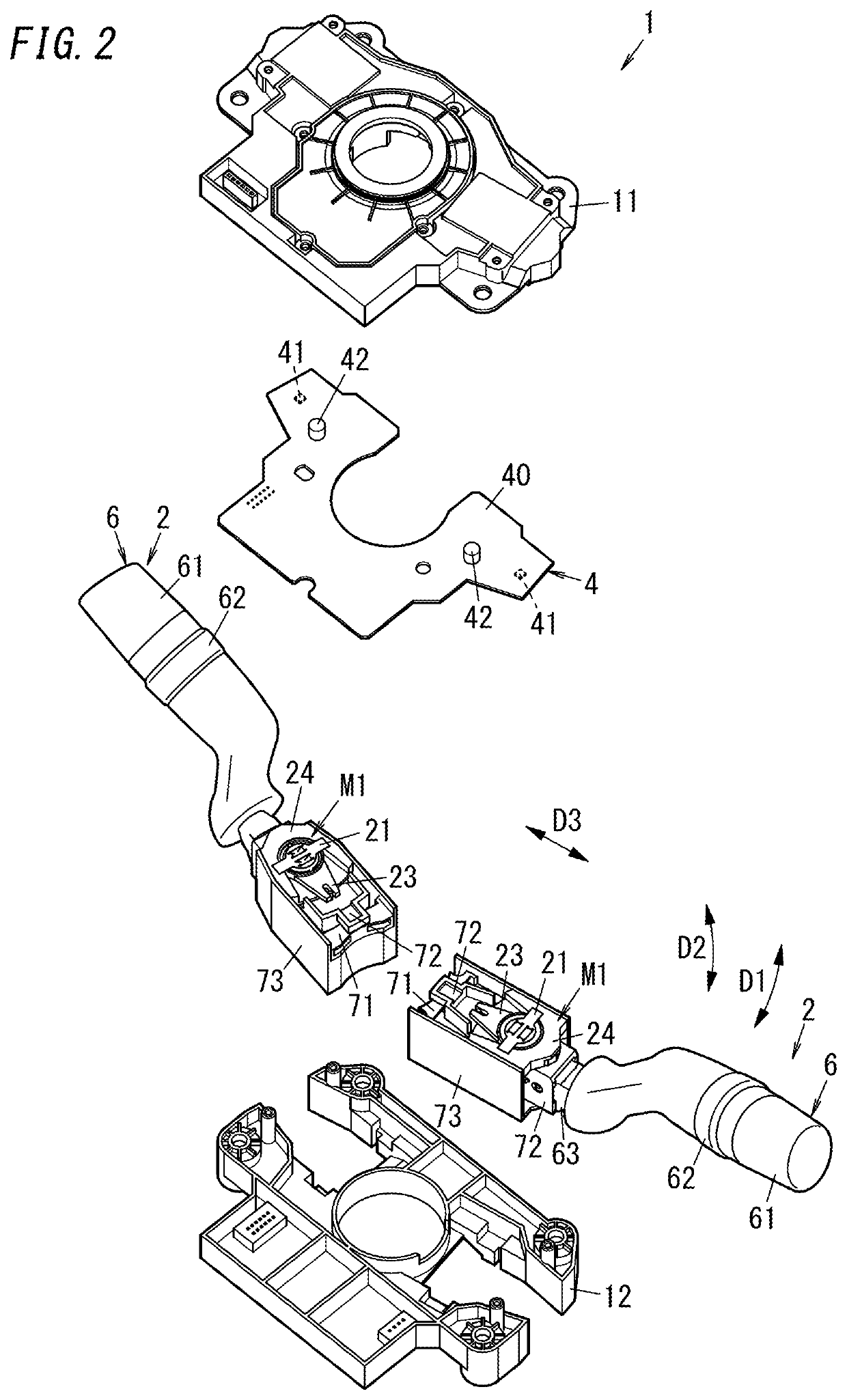
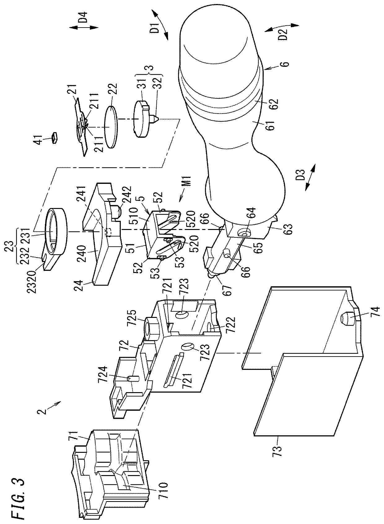
[0025]As shown in FIGS. 1 to 3, the input device 1 of the present embodiment includes a permanent magnet 31, a magnetic sensor 41, an operating unit 6, and a conversion mechanism M1. The magnetic sensor 41 detects a magnetic field produced by the permanent magnet 31. The conversion mechanism M1 converts a movement of the operating unit 6 into a movement of a movable member which is one of the permanent magnet 31 or the magnetic sensor 41 relative to the other of the permanent magnet 31 or the magnetic sensor 41. In other words, the conversion mechanism M1 converts the movement of the operating unit 6 into one of a movement of the magnetic sensor 41 relative to the permanent magnet 31 or a movement of the permanent magnet 31 relative to the magnetic sensor 41. The magnetic sensor 41 outputs a signal according to: a relative angle of rotation of the permanent magnet 31 around a rotation axis X1 (see FIG. 5) relative to the magnetic sensor 41; and strength of a magnet...


PUM


Abstract

An input device includes a permanent magnet, a magnetic sensor, an operating unit, and a conversion mechanism. A movable member is one of the permanent magnet or the magnetic sensor. The conversion mechanism is configured to convert a movement of the operating unit in a first direction into a first action of the movable member and convert a movement of the operating unit in a second direction into a second action of the movable member. The first action is a movement involving a change in a relative angle of rotation of the permanent magnet around a rotation axis relative to the magnetic sensor. The second action is a movement involving a change in the strength of the magnetic field applied to the magnetic sensor.

Description

CROSS-REFERENCE TO RELATED APPLICATIONS[0001]The present application is a Bypass Continuation of International Application No. PCT / JP2021 / 053980 filed on Aug. 3, 2021, which is based upon and claims the benefit of priority to Japanese Patent Application No. 2019-170753, filed on Sep. 19, 2019, the entire contents of both applications are incorporated herein by reference.TECHNICAL FIELD[0002]The present disclosure generally relates to input devices and movable objects and specifically relates to an input device including a magnetic sensor and a movable object including the input device.BACKGROUND ART[0003]JP 2016-012466 A describes a lever switching device (an input device) including an operation lever (an operating unit), a magnet (a permanent magnet), and two detectors (magnetic sensors). The operation lever is rotationally movable in a direction of a first rotation operation (a turn operation) around a first rotation axis and a direction of a second rotation operation (a dimmer op...

Claims


Application Information

Patent Timeline
IPC IPC(8): H01H36/00
CPCH01H36/008B60R16/02G01D5/245H01H19/02
Inventor NISHINAKAMA, HIDEKI
Owner PANASONIC INTELLECTUAL PROPERTY MANAGEMENT CO LTD
Why Eureka
Try Eureka