
Boat Lift Limit Switch

a limit switch and boat technology, applied in waterborne vessels, slipways, transportation and packaging, etc., can solve the problems of unduly bulky devices, interference with boat positioning, and the limit switch employed on conventional post lifts tends to exhibit a number of problems

Pending Publication Date: 2022-06-09
GOLDEN WILLIAM
View PDF0 Cites 0 Cited by
  • Summary
  • Abstract
  • Description
  • Claims
  • Application Information

AI Technical Summary

Benefits of technology

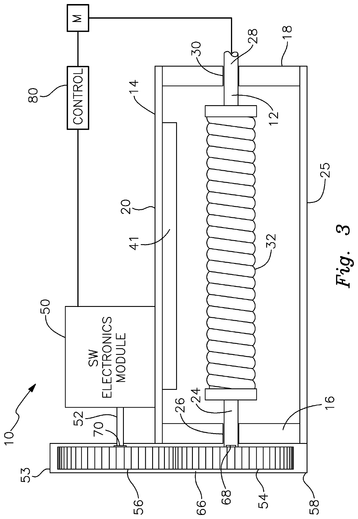
The present invention provides a boat lift limit switch device that is compact, ergonomic, and low profile. It does not interfere with the operation of boats or impede the movement of people in the vicinity of the boat lift. The device features a significantly improved gear mechanism that reduces the risk of gear overheating and disengagement during operation of the boat lift, as well as a more compact and ergonomic integration of the electronics and gear mechanism with the drive shaft of the boat lift. The limit switch includes an electronic module and a gear mechanism that interconnects the electronic module and the drive shaft, directing the electronic module to generate signals that control a motor to stop operation of the lift when a predetermined rotation count and corresponding vertical position is reached. The gear mechanism is designed to prevent lateral disengagement of the gears and discomfort for users.

Problems solved by technology

Limit switches employed on conventional post lifts tend to exhibit a number of problems.
These devices are unduly bulky and frequently interfere with positioning the boat in its slip or on the lift.
The vessel risks striking the limit switch which can cause damage to the switch and / or to the boat.
Unwieldy limit switch devices can also intrude on the free and unhindered movement of boat operators, passengers and service personnel in the vicinity of the lift and supported vessel.
Existing boat lift limit switch devices are further subject to occasional failure, particularly when they become overheated.
If the gears overheat excessively, they are apt to disengage, which will disrupt the required shaft rotation count.
As a result, in such situations, the limit switch device will not work.
This can result in potential damage to the boat lift and / or the supported vessel.
The gears in conventional limit switches present an even greater risk of disengagement and resultant switch failure due to the excessive width of the housing in which those gears are accommodated.
This is especially apt to occur when the gears are overheated.
Once again, this is likely to cause the switch to fail.

Method used


Image

  • Boat Lift Limit Switch
  • Boat Lift Limit Switch
  • Boat Lift Limit Switch

Examples


Embodiment Construction

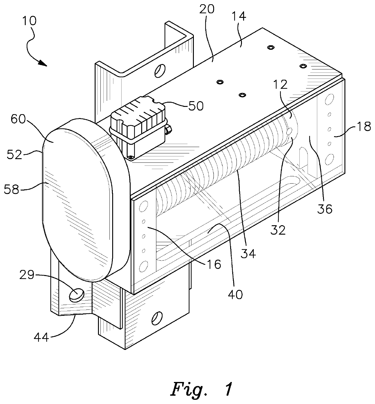
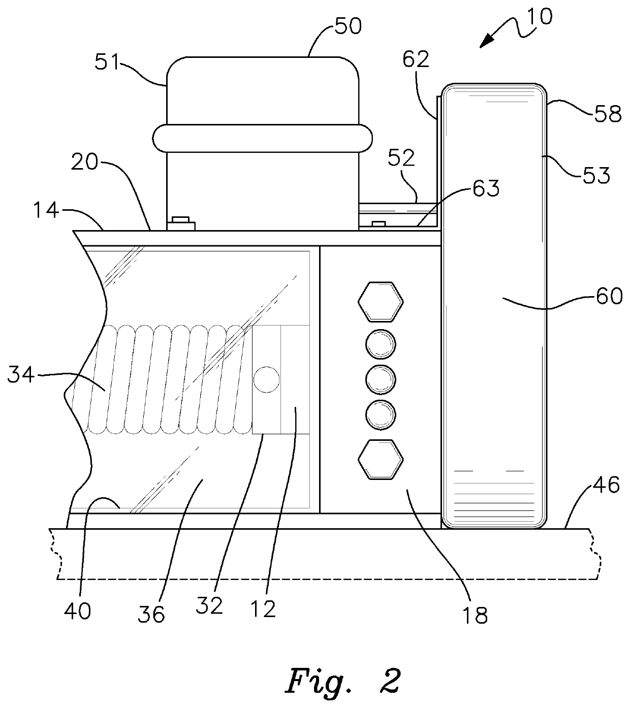
[0016]There is shown in FIGS. 1-4 a boat lift limit switch device 10 that is operatively connected to a cable winder-supporting drive shaft 12 of the lift. The version depicted in FIG. 2 is largely analogous to that shown in FIGS. 1, 3 and 4 and identical reference numerals are used for corresponding parts. In FIGS. 1, 3 and 4 switch 10 is shown mounted proximate the left hand end of drive shaft 12, whereas FIG. 2 shows the switch positioned at the right hand end of shaft 12. Other minor differences are described below. The overall boat lift may employ various structural components such as one or more motors, winders and cables, a platform or frame featuring components including bunk boards and cradle beams, and other structural components (e.g. beams, posts and extrusions) that will be understood to persons skilled in the boat lift art. Limit switch device 10 may be used with assorted varieties of boat lifts featuring different types of drive mechanisms and power systems. The type,...


PUM


Abstract

A limit switch device for a boat lift includes a lower gear connected to and rotated by a drive shaft of the boat lift, and an interengaged upper gear operatively connected to an electronics module of the limit switch. The interengaged gears are enclosed within a gear housing that is sufficiently narrow to restrict the gears from laterally disengaging one another. The limit switch electronics module is mounted above the drive shaft and disposed interiorly of the gear mechanism. The module does not protrude beyond the frame bearing blocks that rotatably support the drive shaft and winder of the boat lift.

Description

RELATED APPLICATION[0001]This application claims the benefit of application Ser. No. 63 / 120,812, filed Dec. 3, 2020.FIELD OF THE INVENTION[0002]This invention relates to a boat lift limit switch and, more particularly, to a switch apparatus that limits the degree to which the vessel-supporting platform of a boat lift may be lowered or raised.BACKGROUND OF THE INVENTION[0003]Boat lifts commonly employ a limit or auto-stop switch to stop operation of the lift when it reaches a predetermined height or vertical position, either during raising or lowering of the lift platform. Limit switches employed on conventional post lifts tend to exhibit a number of problems. These devices are unduly bulky and frequently interfere with positioning the boat in its slip or on the lift. The vessel risks striking the limit switch which can cause damage to the switch and / or to the boat. Unwieldy limit switch devices can also intrude on the free and unhindered movement of boat operators, passengers and se...

Claims


Application Information

Patent Timeline
IPC IPC(8): B63C3/06
CPCB63C3/06
Inventor GOLDEN, WILLIAM
Owner GOLDEN WILLIAM
Learn More