Anode stack

a technology of anodes and stacks, applied in the direction of x-ray tubes, x-ray tube targets and convertors, x-ray tube target materials, etc., can solve the problems of device failure, low efficiency of x-ray tubes, and usually less than 1% of x-ray production, so as to reduce electrical arcing and electrical breakdown

Active Publication Date: 2018-02-22
OXFORD INSTR X RAY TECH INC
View PDF1 Cites 0 Cited by
  • Summary
  • Abstract
  • Description
  • Claims
  • Application Information

AI Technical Summary

Benefits of technology

[0007]The present inventors have recognised that an improved and more reliable anode stack is required, which provides for reduced electrical arcing and electrical breakdown in the X-ray device.

Problems solved by technology

However, efficiency of the X-ray tube is very low and the yield of X-ray production is usually less than 1%, with the remaining 99% of the input energy being converted into heat.
However, this design has a number of drawbacks related to high electric fields at the triple point region, i.e. the region where the dielectric, metal and vacuum meet; the electric field at the triple point regions of traditional anode stacks can be much greater than the surrounding electric field depending on the geometry of the component parts of the anode stack and the dielectric constants of the materials.
These locally intensified electric fields are often the cause of electrical arcing and electrical breakdown that ultimately leads to device failure.

Method used


Image

  • Anode stack
  • Anode stack
  • Anode stack

Examples


Embodiment Construction

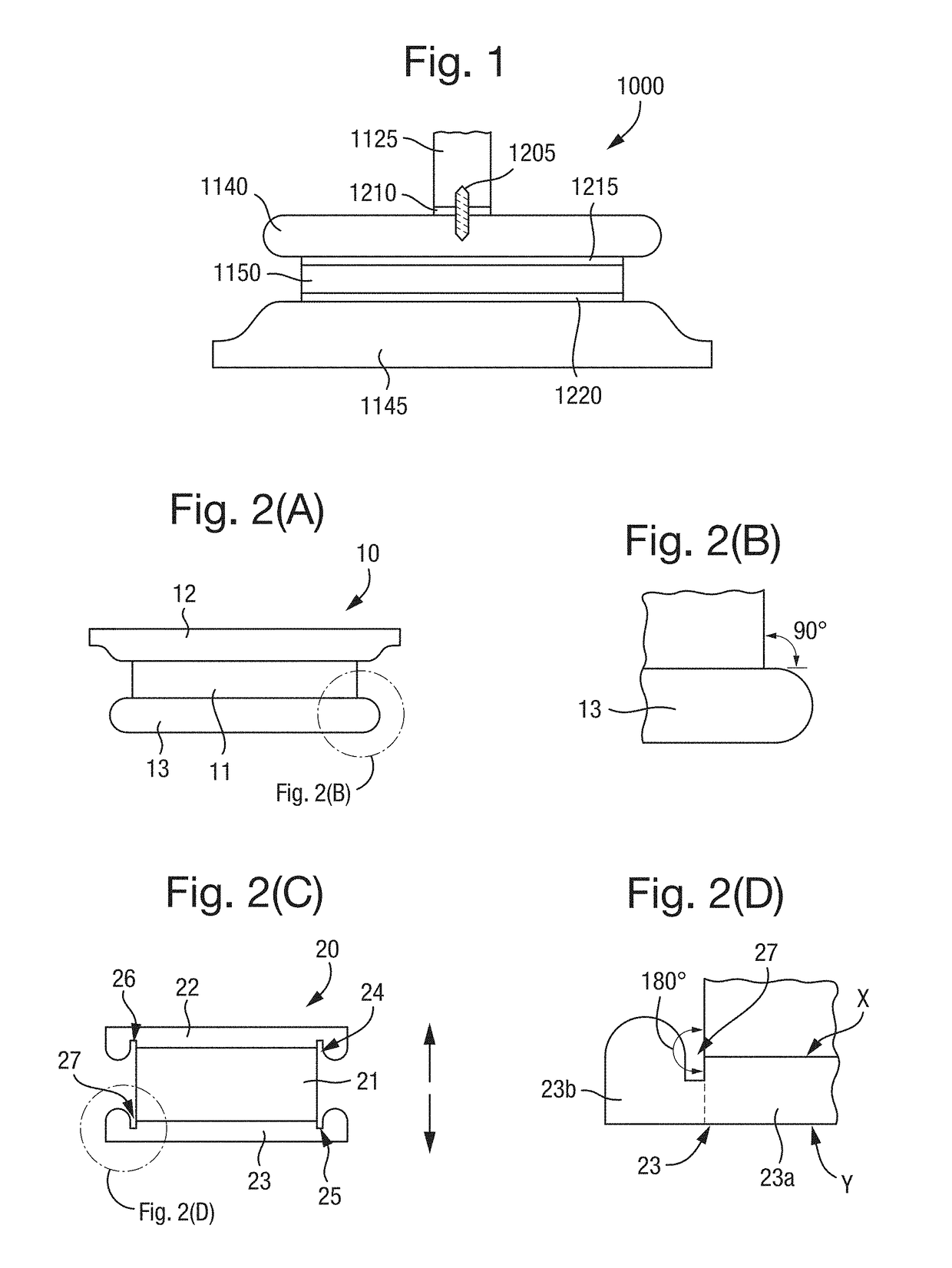
[0041]A representation of a prior art anode stack 1000 is shown in FIG. 1. In this figure, two metal conductor plates 1140, 1145 are joined to a dielectric plate 1150 to form a thermally conductive and electrically insulated device for removing heat that is generated in an X-ray tube. Bonding layers 1215, 1220, 1210 are used to join the metal conductor plates 1140, 1145 to the dielectric plate 1150 and for joining the upper conductor plate 1140 to the high voltage anode 1125. A screw 1205 is also used to provide mechanical support between the upper conductor plate 1140 and the high voltage anode 1125.

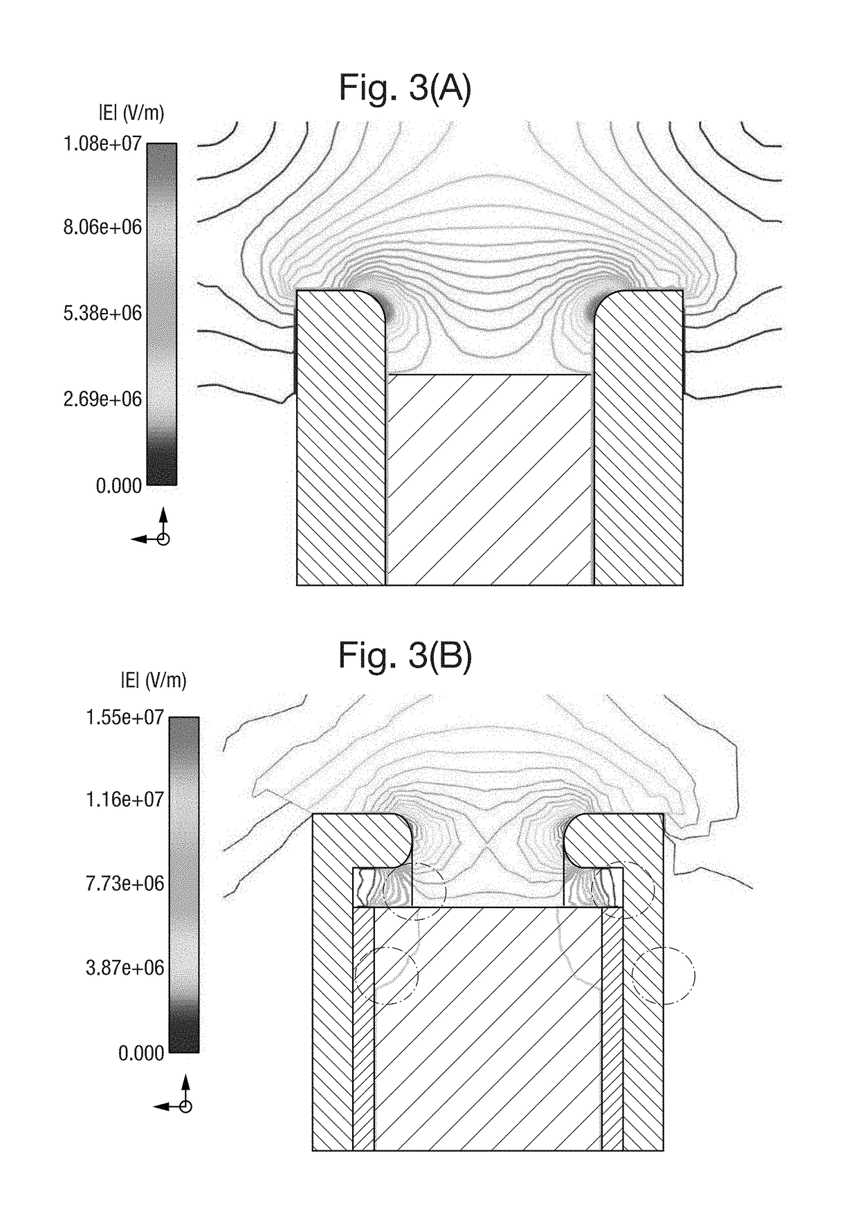
[0042]Although this thermal management system overcomes some of the disadvantages of oil based cooling systems, it also introduces some disadvantages itself. In particular, the perpendicular angles at the edges of the interface between the dielectric 1150 and conductor plates 1140, 1145 causes high electric field strengths to exist at the respective triple point regions, i.e. the region...


PUM


Abstract

There is provided an anode stack for cooling and electrically insulating a high voltage anode of an X-ray device. The anode stack has at least a conductor member and a dielectric member, and the conductor member has a main body and a peripheral portion. The dielectric member overlies and couples with the main body of the conductor member at one surface. At an opposing surface of the main body of the conductor member, an end of the high voltage anode is coupled thereto in use. The peripheral portion of the conductor member has an annular region that surrounds at least a part of the dielectric member and which is spaced therefrom.

Description

TECHNICAL FIELD[0001]The present invention relates to an anode stack and in particular it relates to an anode stack for cooling and electrically insulating a high voltage anode of an X-ray device.BACKGROUND OF THE INVENTION[0002]An X-ray tube is a type of vacuum tube that converts electrical power into X-rays. In such devices, the cathode is a negatively charged electron emitter and the anode is a positively charged electron collector. Between the cathode and the anode, a flow of electrical current is established using a high voltage power source, typically between 4 kV and 500 kV, which accelerates the electrons in their path. However, efficiency of the X-ray tube is very low and the yield of X-ray production is usually less than 1%, with the remaining 99% of the input energy being converted into heat.[0003]The excess heat that is produced in the X-ray tube must be removed from the high voltage anode in order to prevent the device from overheating and to enable continuous operation...

Claims


Application Information

Patent Timeline
Patent Type & Authority Applications(United States)
IPC IPC(8): H01J35/12
CPCH01J35/12H01J2235/1291H01J2235/1204H01J2235/081H01J2235/165
Inventor ROGER, JOSEPHFOWLER, CHARLES L.CHIDAMBARAM, MAHENDRANALIVOV, YAHYA
Owner OXFORD INSTR X RAY TECH INC
Why Eureka
Try Eureka