Watertight testing device

Pending Publication Date: 2022-06-23
KUBOTA LTD
View PDF0 Cites 1 Cited by
  • Summary
  • Abstract
  • Description
  • Claims
  • Application Information

AI Technical Summary

Benefits of technology

The present invention is a watertight testing device that improves sealing performance between the outer surface of a core and the inner surface of a pipe when a watertight test is conducted. The device includes a moving-range regulating member that limits an excessive movement of the first and second pressing members beyond the release position in the release direction. The core is set in the pipe joint part, and the moving device moves the first and second pressing members in the pipe axial direction, so that the first pressing member presses and compresses the first seal member into the first seal-member insertion space, and the second pressing member presses and compresses the second seal member into the second seal-member insertion space. This results in a compressed first seal member providing sufficient sealing between the outer surface of the core and the inner surface of the one pipe, and a compressed second seal member providing sufficient sealing between the outer surface of the core and the inner surface of the other pipe, improving seal performance between the outer surface of the core and the inner surface of the pipe.

Problems solved by technology

Unfortunately, this may reduce sealing performance between the outer surface of the cylindrical body 201 and the inner surfaces of the pipes 202 and 204 when a watertight test is conducted.

Method used


Image

  • Watertight testing device
  • Watertight testing device
  • Watertight testing device

Examples


first embodiment

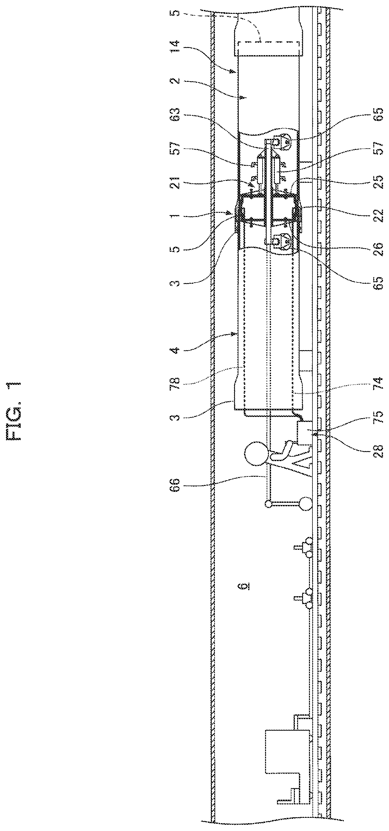
[0047]In a first embodiment, as illustrated in FIG. 1, reference numeral 1 denotes a pipe joint where a socket 3 of one pipe 2 receives an inserted spigot 5 of the other pipe 4. The pipes 2 and 4 are, for example, PN pipes made of ductile. The pipes 2 and 4 are disposed to be joined to each other in a pipeline construction shaft 6 formed in the ground and constitute a pipeline 14.

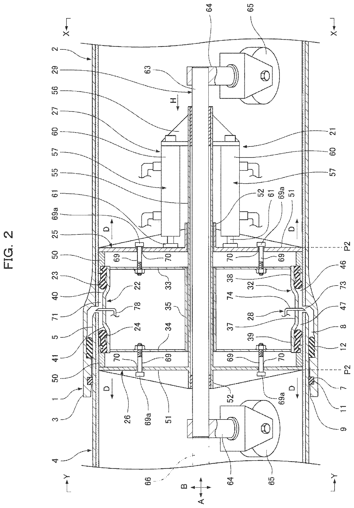
[0048]As illustrated in FIG. 2, the inner surface of the socket 3 has a lock-ring storage groove 7 and a seal-member attachment recess 8. The lock-ring storage groove 7 is located between the seal-member attachment recess 8 and an opening end 9 of the socket 3 in a pipe axial direction A.

[0049]The lock-ring storage groove 7 accommodates a lock ring 11 for preventing removal. In the seal-member attachment recess 8, an annular seal member 12 made of an elastic material such as rubber is attached. The seal member 12 is interposed between the inner surface of the socket 3 and the outer surface of the spigot 5 a...

second embodiment

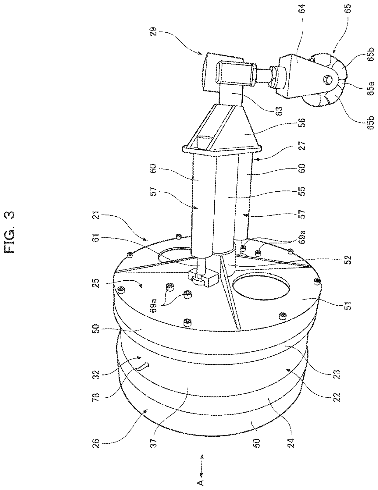
[0090]In the second embodiment, as illustrated in FIG. 12, a pressing part 50 of a first pressing member 25 and a proximal-end part 31 of a first seal member 23 are connected to each other with a plurality of screws 85, thereby engaging the first seal member 23 and the first pressing member 25 in a pipe axial direction A. Likewise, a pressing part 50 of a second pressing member 26 and a proximal-end part 31 of a second seal member 24 are connected to each other with a plurality of screws 85, thereby engaging the second seal member 24 and the second pressing member 26 in the pipe axial direction A.

[0091]In the foregoing embodiments, as illustrated in FIG. 2, the movable rod 55 is attached to the second pressing member 26 and penetrates the backside of the first pressing member 25, and the receiving member 56 is opposed to the first pressing member 25. The movable rod 55 may be attached to the first pressing member 25 and penetrate the back side of the second pressing member 26, and t...


PUM


Abstract

A watertight testing device includes a cylindrical core fit into a pipe joint part, a first seal member for sealing between the outer surface of the core and the inner surface of one pipe, a second seal member for sealing between the outer surface of the core and the inner surface of the other pipe, a first pressing member for pressing and compressing the first seal member into a first seal-member insertion space, a second pressing member for pressing and compressing the second seal member into a second seal-member insertion space, a moving device for moving the first and second pressing members in a pipe axial direction, and a test fluid feeder for feeding a test fluid into a test space.

Description

FIELD OF THE INVENTION[0001]The present invention relates to a watertight testing device used for a watertight test of a pipe joint part provided with a seal member between the inner surface of a socket and the outer surface of a spigot with the spigot inserted into the socket.BACKGROUND OF THE INVENTION[0002]Conventionally, as illustrated in, for example, FIGS. 13 and 14, such a watertight testing device includes a cylindrical body 201 fit into a pipe joint part 200, an annular first water-stop bag 203 that is expandable and shrinkable to provide sealing between the outer surface of one end of the cylindrical body 201 and the inner surface of one pipe 202, an annular second water-stop bag 205 that is expandable and shrinkable to provide sealing between the outer surface of the other end of the cylindrical body 201 and the inner surface of the other pipe 204, an injection pipe 206 for injecting compressed air into the first and second water-stop bags 203 and 205 so as to expand the ...

Claims


Application Information

Patent Timeline
IPC IPC(8): G01M3/04F16J15/10
CPCG01M3/04F16J15/10F16L55/1283F16L55/132G01M3/005
Inventor KISHI, SHOZOKOMARU, YUITOKAMACHI, KOJISHIMOMURA, MASATAKA
Owner KUBOTA LTD
Why Eureka
Try Eureka