Surgical connector for dental fixture

a surgical and fixture technology, applied in dental surgery, medical science, osteosynthesis devices, etc., can solve the problems of inconvenient picking up of fixtures, damage to surrounding teeth or bones, etc., and achieve the effect of convenient and fast insertion into the insertion hole and easy picking up

Pending Publication Date: 2022-07-14
MEGAGEN IMPLANT
View PDF0 Cites 0 Cited by
  • Summary
  • Abstract
  • Description
  • Claims
  • Application Information

AI Technical Summary

Benefits of technology

[0025]According to the inventive concept, when the connector head portion is inserted into the insertion hole provided in the fixture, as the entrance guide portion for guiding the entrance of the connector head porti

Problems solved by technology

In the case of a general prosthesis or denture, surrounding teeth or bones may be damaged as time passes.
However, according to the related art, as the outer wall of the head portion of the dental fixture operation connector and the inner wall of the insertion hole

Method used


Image

  • Surgical connector for dental fixture
  • Surgical connector for dental fixture
  • Surgical connector for dental fixture

Examples


first embodiment

[0026]FIG. 1 schematically illustrates a placement process of a fixture of a dental implant using a dental fixture operation connector according to the present inventive concept.

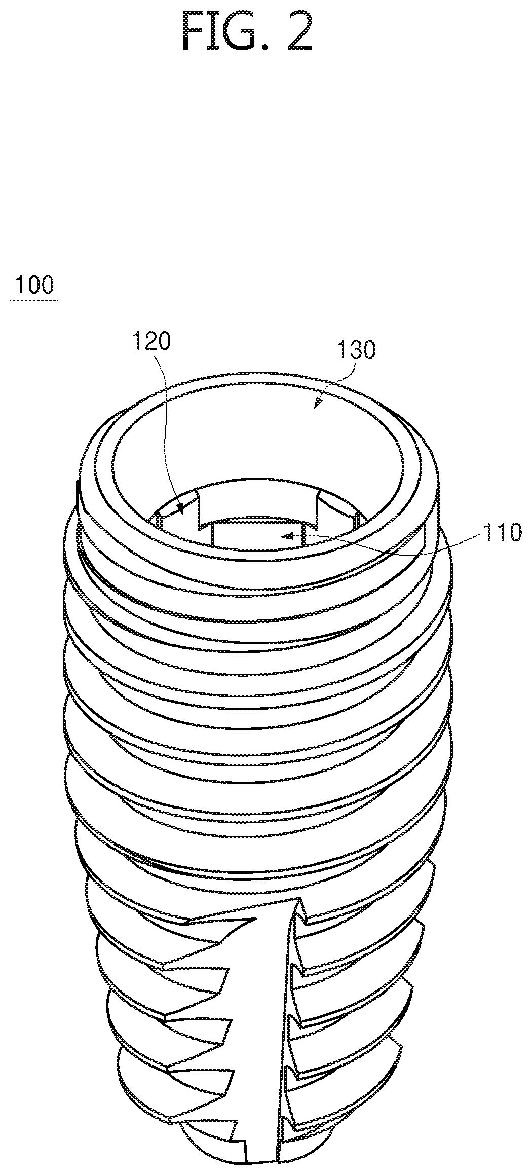
[0027]FIG. 2 illustrates the fixture of the dental implant of FIG. 1.

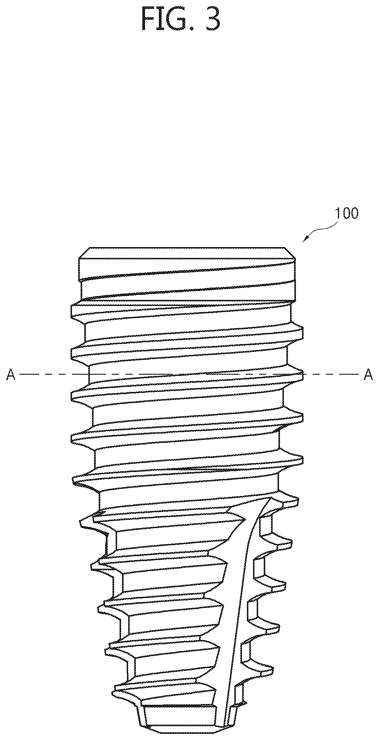
[0028]FIG. 3 is a front side view of FIG. 2.

[0029]FIG. 4 illustrates a section taken along a line A-A of FIG. 3.

[0030]FIG. 5 illustrates the inside of the fixture of FIG. 3.

[0031]FIG. 6 illustrates a dental fixture operation connector that picks up the fixture of FIG. 2.

[0032]FIG. 7 illustrates a connector head portion of FIG. 6.

[0033]FIG. 8 is a bottom view of FIG. 6.

[0034]FIG. 9 illustrates an elastic pressing body that is inserted into an accommodation groove of FIG. 7.

[0035]FIG. 10 is an operation state view illustrating a state in which the connector head portion of FIG. 7 is inserted into the fixture.

second embodiment

[0036]FIG. 11 illustrates a dental fixture operation connector according to the present inventive concept.

MODE OF THE INVENTIVE CONCEPT

[0037]The attached drawings for illustrating exemplary embodiments of the inventive concept are referred to in order to gain a sufficient understanding of the inventive concept and the merits thereof.

[0038]Hereinafter, the inventive concept will be described in detail by explaining exemplary embodiments of the inventive concept with reference to the attached drawings. In the following description, when detailed descriptions about related well-known functions or structures are determined to make the gist of the disclosure unclear, the detailed descriptions will be omitted herein.

[0039]FIG. 1 schematically illustrates a placement process of a fixture of a dental implant using a dental fixture operation connector according to a first embodiment of the present inventive concept. FIG. 2 illustrates the fixture of the dental implant of FIG. 1. FIG. 3 is a ...


PUM


Abstract

A dental fixture operation connector is disclosed. The dental fixture operation connector may include a connector body portion, a connector head portion connected to the connector body portion and inserted into an insertion hole formed in an upper end area of a fixture, and an entrance guide portion provided in the connector head portion and guiding entrance of the connector head portion when the connector head portion is inserted into the insertion hole.

Description

TECHNICAL FIELD[0001]The inventive concept relates to a surgical connector for a dental fixture, and more particularly, to a surgical connector for a dental fixture that is capable of placing a fixture in an alveolar bone by easily picking up the fixture from a fixture storing ample where the fixture is stored.BACKGROUND ART[0002]An implant originally means a substitute used to restore lost human tissues. In a dental field, however, the implant refers to a series of procedures to transplant an artificial tooth.[0003]To replace a lost dental root, the implant is a series of dental procedures to restore the function of a tooth by placing a fixture, which is a dental root formed of titanium and having no rejection to a human body, in an alveolar bone where a tooth is lost, and then fixing an artificial tooth thereto.[0004]In the case of a general prosthesis or denture, surrounding teeth or bones may be damaged as time passes. In contrast, since the implant does not harm the surrounding...

Claims


Application Information

Patent Timeline
IPC IPC(8): A61C8/00
CPCA61C8/006A61C8/0022A61C8/0089A61C1/14A61C1/145A61C3/00A61C8/00A61B17/888A61B17/8888
Inventor PARK, KWANG BUM
Owner MEGAGEN IMPLANT
Why Eureka
Try Eureka