Carrier tape and pack

a carrier tape and tape strip technology, applied in the field of carrier tape, can solve the problem that the embossed portion cannot be easily picked up, and achieve the effect of convenient picking up

Active Publication Date: 2018-04-17
NICHIA CORP
View PDF17 Cites 0 Cited by
  • Summary
  • Abstract
  • Description
  • Claims
  • Application Information

AI Technical Summary

Benefits of technology

[0005]A carrier tape for accommodating an LED according to one embodiment of the present invention includes a sheet defining a recessed embossed portion that can accommodate the LED which includes a light emitting portion. The light emitting portion has light-transmissive resin, and is arranged on the side surface of the LED as viewed in plan view. The embossed portion includes a protruding part that is arranged on one of the interior surfaces of the recessed embossed portion and can face the light emitting portion of the LED. Depressed parts are provided on the both sides of the protruding part so that the depressed surfaces can be spaced away from the LED when the LED is accommodated in the embossed portion. The width of the protruding part is smaller than the width of the light emitting portion of the LED as viewed in plan view.
[0007]According to the above, it is possible to provide a carrier tape from which LEDs can be easily picked up.

Problems solved by technology

In the case where such a low-hardness resin material is used in the side light emission type LED, the LED may not be easily picked up from the embossed portion.

Method used


Image

  • Carrier tape and pack
  • Carrier tape and pack
  • Carrier tape and pack

Examples


first embodiment

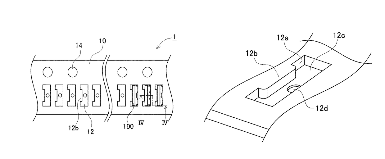
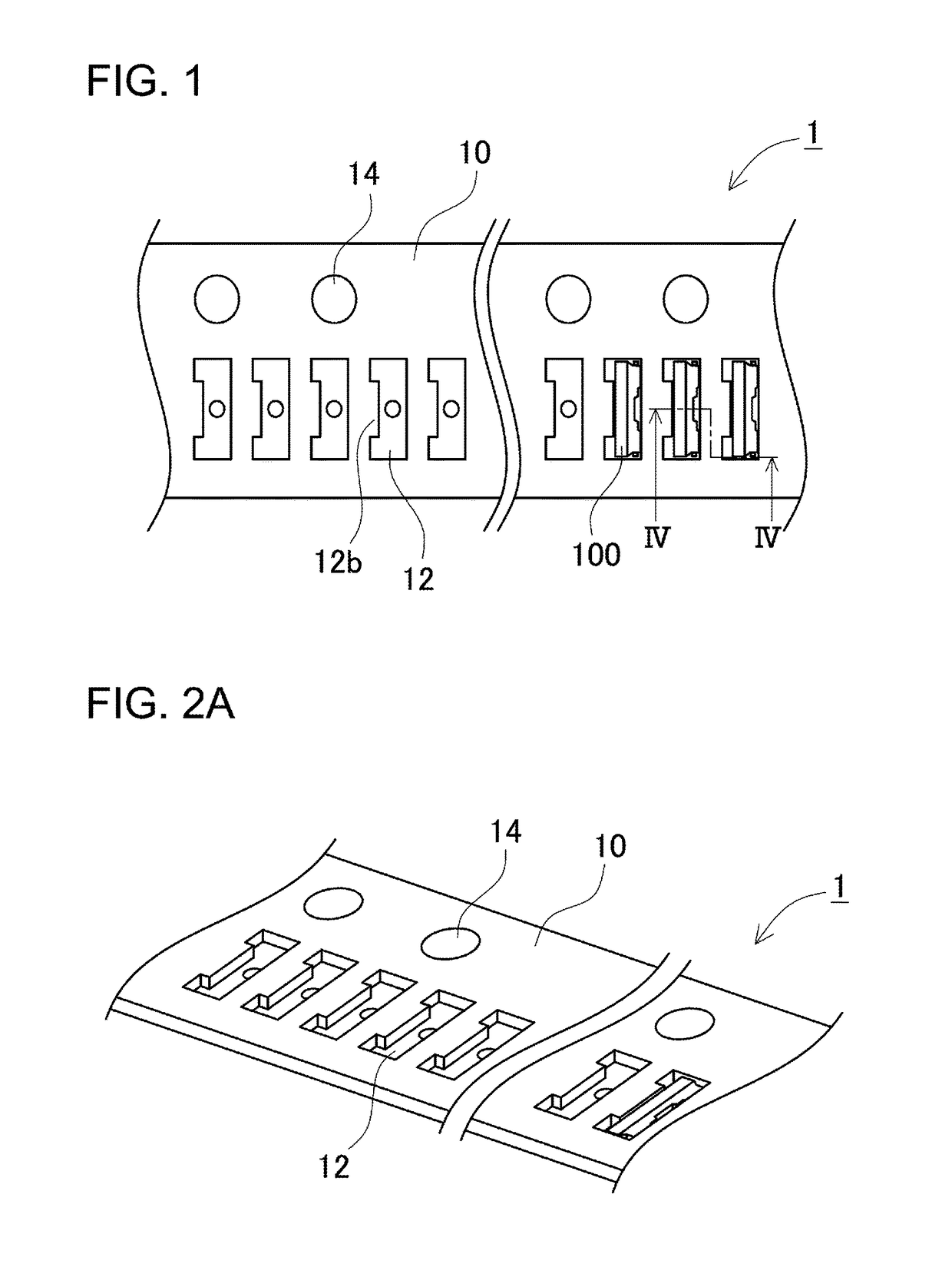
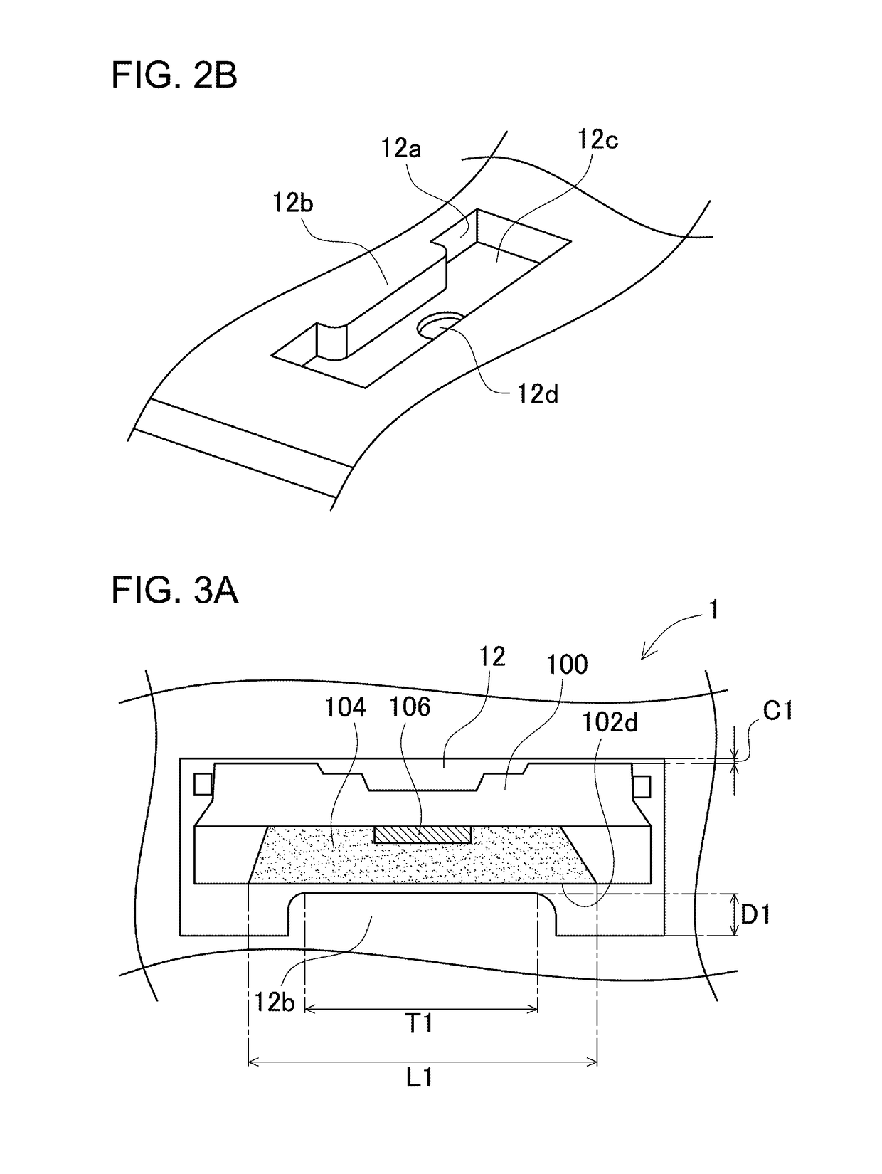
[0053]FIG. 1 is a schematic plan view showing a part of a pack which includes the carrier tape 10 and the LEDs 100 accommodated in some of the embossed portions 12 of the carrier tape 10 according to a first embodiment of the present invention. FIG. 2A is a perspective view of the pack. FIG. 2B is an enlarged view of the embossed portion shown in FIG. 2A. FIGS. 3A to 3C are plan views of the embossed portions 12 and the LEDs 100 accommodated in these embossed portions with the LEDs 100 being shown in cross section for schematically illustrating their internal structures. FIG. 4 shows a cross-sectional view of the carrier tape and the LEDs taken along the stepped line IV-IV which passes through the center of one embossed portion and the lateral end part of other embossed portion in FIG. 1. In FIG. 4, the left-side cross-sectional part is taken along one segment of the line IV-IV that passes through the light emitting element, and the shaded interior surfaces of the embossed portion s...

second embodiment

[0057]FIG. 7 is a schematic plan view showing a carrier tape 20 and an LED 200 to be accommodated in its embossed portion 22 according to a second embodiment of the present invention. The LED 200 has a recessed portion 202c, which is arranged at a location on its lateral surface deviated to the top side and serves as the light emitting portion 202d. A protruding part 22b of the interior surface of the embossed portion 22 is correspondingly arranged at the location which is deviated to the top side and faces the light emitting portion 202d. That is, the protruding part has a height smaller than the depth of the embossed portion 22.

[0058]A carrier tape according to the present invention can be used as carrier types for LEDs to be used as a light source for lighting, light sources for various types of indicators, a light source for vehicle, a light source for liquid crystal display back light, and a light source for sensor.


PUM


Abstract

A carrier tape is provided from which LEDs can be easily picked up. A carrier tape for accommodating an LED includes a sheet defining recessed embossed portions that can accommodate the LED. The embossed portion is formed to accommodate the LED which includes a light emitting portion having light-transmissive resin and arranged on its lateral surface as viewed in plan view. The embossed portion includes a protruding part that is arranged on one of the interior surfaces of the recessed embossed portion and can face the light emitting portion of the LED. Depressed parts are provided on the both sides of the protruding part so that the depressed surfaces can be spaced away from the LED when the LED is accommodated in the embossed portion. The width of the protruding part is smaller than the width of the light emitting portion of the LED as viewed in plan view.

Description

CROSS-REFERENCE TO RELATED APPLICATIONS[0001]The present application claims priority under 35 U. S. C. § 119 to Japanese Patent Application No. 2015-016,311, filed Jan. 30, 2015; and Japanese Patent Application No. 2015-255,503, filed Dec. 26, 2015. The contents of this application are incorporated herein by reference in their entirety.BACKGROUND1. Technical Field[0002]The present invention relates to a carrier tape for accommodating an LED, and a pack including a carrier tape and an LED accommodated in the carrier tape.2. Description of Related Art[0003]Some electronic parts such as LEDs (i.e., Light Emitting Diodes) are accommodated in embossed portions (recessed portions) of embossed carrier tapes (hereinafter, also simply referred to as “carrier tapes”) for storage and shipping. In known carrier tapes, the various sizes and shapes of embossed portions are selected according to the sizes and shapes of electronic parts to be accommodated in the embossed portions (see Laid-Open Pat...

Claims


Application Information

Patent Timeline
Patent Type & Authority Patents(United States)
IPC IPC(8): H01L21/683B65D73/02
CPCH01L21/6836B65D73/02H01L2221/68313H01L33/48H01L33/54
Inventor IWAKADO, NAOKITAMURA, YOSUKESHIBANO, YUKIHIROMINAMOTO, WATARU
Owner NICHIA CORP
Why Eureka
Try Eureka