Integrated circuit tag

a technology of integrated circuits and tags, applied in the field of integrated circuit (ic) tags, can solve the problems of inability to apply product batches, and achieve the effects of convenient installation, easy picking up, and prevention of damage to the main body of ic tags

Inactive Publication Date: 2010-01-21
MITSUBISHI HEAVY IND PRINTING & PACKAGING MACHINERY
View PDF5 Cites 0 Cited by
  • Summary
  • Abstract
  • Description
  • Claims
  • Application Information

AI Technical Summary

Benefits of technology

[0020]According to the IC tag of the present invention, the plate of the IC tag has at its one ends the protrusions extending from the flat portion, so if the IC tag is held through the protrusions when placing it onto a batch of sheet products handled in batch units or when collecting it from the product batch, the IC tag can be easily picked up. In addition, even when a sheet product etc. drop down to the IC tag on a batch of sheet products, the sheet product collides with the protrusion, and the direct collision with the IC tag main body installed on the flat portion of the IC tag is avoided. Consequently, the joined portion between the plate and the IC tag main body, and the IC tag main body itself, are protected.
[0021]If the IC tag main body is embedded in the plate, damage to the IC tag main body can be prevented. If the IC tag main body is stuck on one surface of the plate, the IC tag main body can be easily installed on an elastic plate.
[0022]If the protrusion is formed by bending the plate, it is flat in shape and can be easily held. Depending on the degree that the protrusion is bent, stacked IC tags can be easily picked up one by one.
[0023]If the protrusions are formed at the opposite ends of the plate, when picking up the IC tag, either or both of the protrusions can be used and therefore operability is enhanced. In addition, even if a sheet product drops down to the IC tag, the joined portion between the plate and the IC tag main body, and the IC tag main body itself can be protected by both protrusions. Still other objects and advantages of the present invention will become readily apparent to those skilled in the art from the following detailed description, wherein the preferred embodiments of the invention are shown and described, simply by way of illustration of the best mode contemplated of carrying out the invention. As will be realized, the invention is capable of other and different embodiments, and its several details are capable of modifications in various obvious aspects, all without departing from the invention. Accordingly, the drawings and description of thereof are to regarded as illustrative in nature, and not as restrictive.

Problems solved by technology

As in patent document 1, if an ID tag is installed on a pallet placing a product batch thereon, the product batch on the pallet can be specified, but since this case is based on the assumption that a pallet is used in conveying or shipping a product batch, the product batch cannot be applied if no pallet is employed.

Method used


Image

  • Integrated circuit tag
  • Integrated circuit tag
  • Integrated circuit tag

Examples


Embodiment Construction

[0053]An embodiment of the present invention will be described hereinafter with reference to the drawings.

Construction of an Embodiment

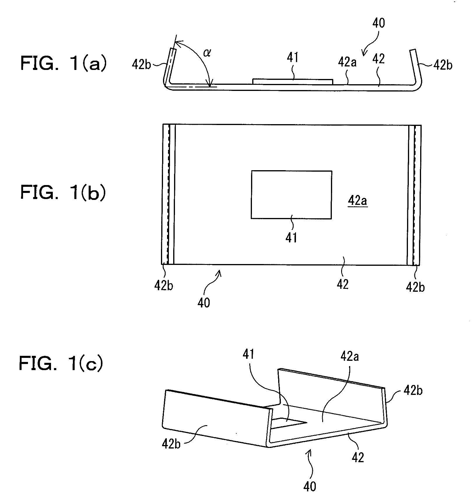
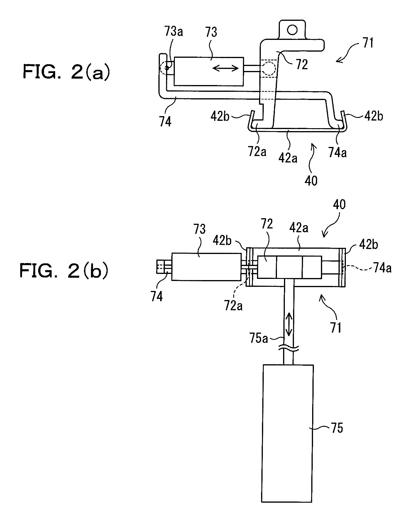
[0054]FIGS. 1 to 6 are used to explain an IC tag and an IC tag holding tool according to an embodiment of the present invention.

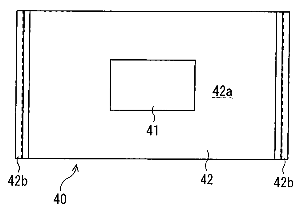
[0055]Referring initially to the IC tag according to this embodiment, as illustrated in FIGS. 1(a) to 1(c), the IC tag 40 is placed on sheet products handled in batch units after production (hereinafter referred to as a product batch) and used to manage this product batch. The IC tag 40 includes an IC tag main body 41 and a plate 42 equipped with the IC tag main body 41. Note that a sheet product in this embodiment is a corrugated board manufactured by a corrugator.

[0056]The IC tag main body 41 is plate shaped base body made of a vinyl sheet, etc., and includes an IC chip and a radio antenna, which are embedded in the IC tag main body 41.

[0057]The plate 42 has a flat portion 42a formed into a rectangular or strip shape with ...


PUM


Abstract

The present invention relates to integrated circuit (IC) tags. The IC tag (40) placed on sheet products handled in batch units after production, and used to manage the sheet products. The IC tag includes an IC tag main body (41) having an IC chip and a radio antenna embedded therein, and a plate (42) with a flat portion (42a) in which the IC tag main body (41) is installed. The plate (42) has at its one end a protrusion (42b) extending from the flat portion (42a). This makes it possible to attach and detach the IC tag to and from the inner side of the paper tube.

Description

CROSS-REFERENCE TO RELATED APPLICATIONS[0001]The present Application is based on International Application No. PCT / JP2008 / 051545, filed on Jan. 31, 2008, which in turn corresponds to Japanese Application No. 2007-021946 filed on Jan. 31, 2007, and priority is hereby claimed under 35 USC § 119 based on these applications. Each of these applications are hereby incorporated by reference in their entirety into the present application.TECHNICAL FIELD[0002]The present invention relates to integrated circuit (IC) tags suitable for use in placing on sheet products such as corrugated boards and corrugated board container blanks handled in batch units after production, and managing the sheet products.BACKGROUND ART[0003]In the case of sheet products including paper products such as corrugated boards and corrugated board container blanks (corrugated board container material at the previous state of assembly)manufactured from the corrugated boards, a predetermined number of stacked sheets are c...

Claims


Application Information

Patent Timeline
Patent Type & Authority Applications(United States)
IPC IPC(8): G06K19/07B31B50/06B31B50/98
CPCB31B1/90B31B2201/90G06K19/07758G06K19/07728G06K19/04B31B50/81B65D25/20G06K19/07
Inventor KATO, TOSHIHIDEKIMURA, MASAKAZUSATO, HIROSHI
Owner MITSUBISHI HEAVY IND PRINTING & PACKAGING MACHINERY
Why Eureka
Try Eureka