

Full DC voltage power backup system for wind turbine
- Summary
- Abstract
- Description
- Claims
- Application Information
AI Technical Summary
Benefits of technology
Problems solved by technology
Method used
Image

Examples
Embodiment Construction
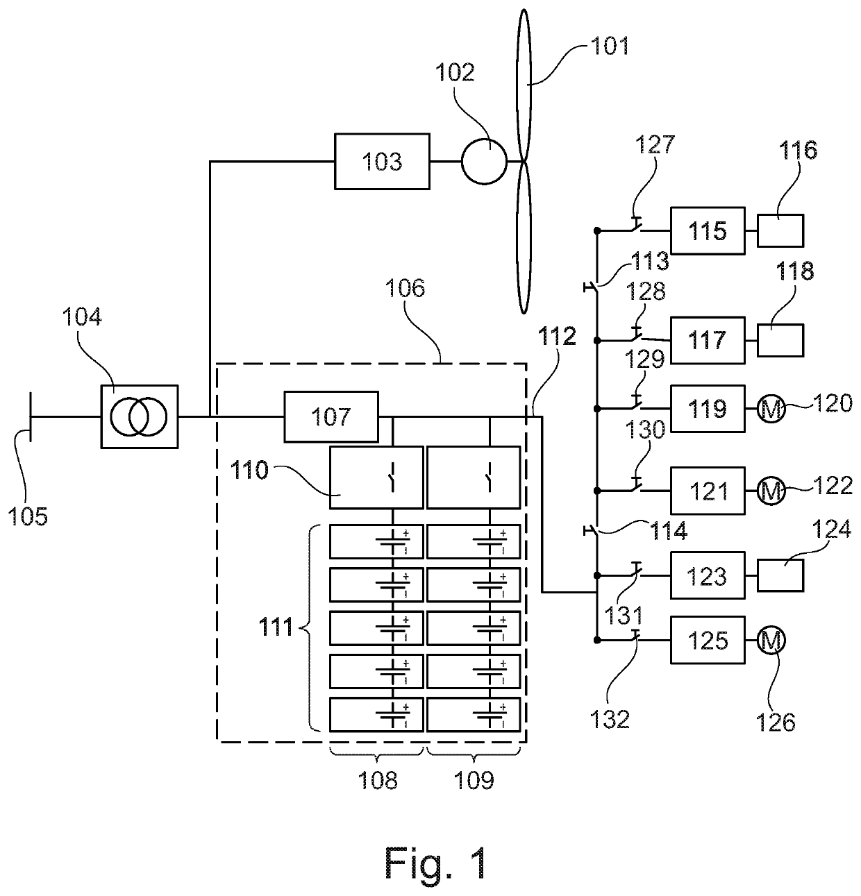
[0033]In a general aspect the present invention relates to a power backup system for supplying power to an internal power supply grid of a wind turbine during a grid fault, such as during a grid loss or a temporary voltage drop. The power backup system comprises a power storage module comprising one or more stacked, i.e. series connected, power storage units providing a total backup voltage that falls within a nominal voltage range of the internal power supply grid of the wind turbine. The total backup voltage refers to the output voltage of the power storage module, which in the embodiment of the series connected power storage units, is the aggregate output voltage of the connected power storage units, which for series connected power storage units is the sum of the individual output voltage of the power storage units. As the total backup voltage falls within the nominal voltage range of the internal power supply grid, the power backup system is directly connected to the internal p...
PUM
 Abstract
Description
Claims
Application Information