
Tidal energy system

A tidal and energy technology, applied in the field of tidal energy systems, can solve problems such as small percentages, reduce construction costs and eliminate large-scale foundation preparations

Inactive Publication Date: 2009-01-21
拉米兹·阿提亚
View PDF3 Cites 0 Cited by
  • Summary
  • Abstract
  • Description
  • Claims
  • Application Information

AI Technical Summary

Problems solved by technology

[0017] While the amount of tidal energy available is huge, the percentage that can be harvested with current technology is very small

Method used


Image

  • Tidal energy system
  • Tidal energy system
  • Tidal energy system

Examples


Embodiment Construction

[0097] Figure 1 to Figure 7 - preferred embodiment

[0098] The components of the tidal energy system

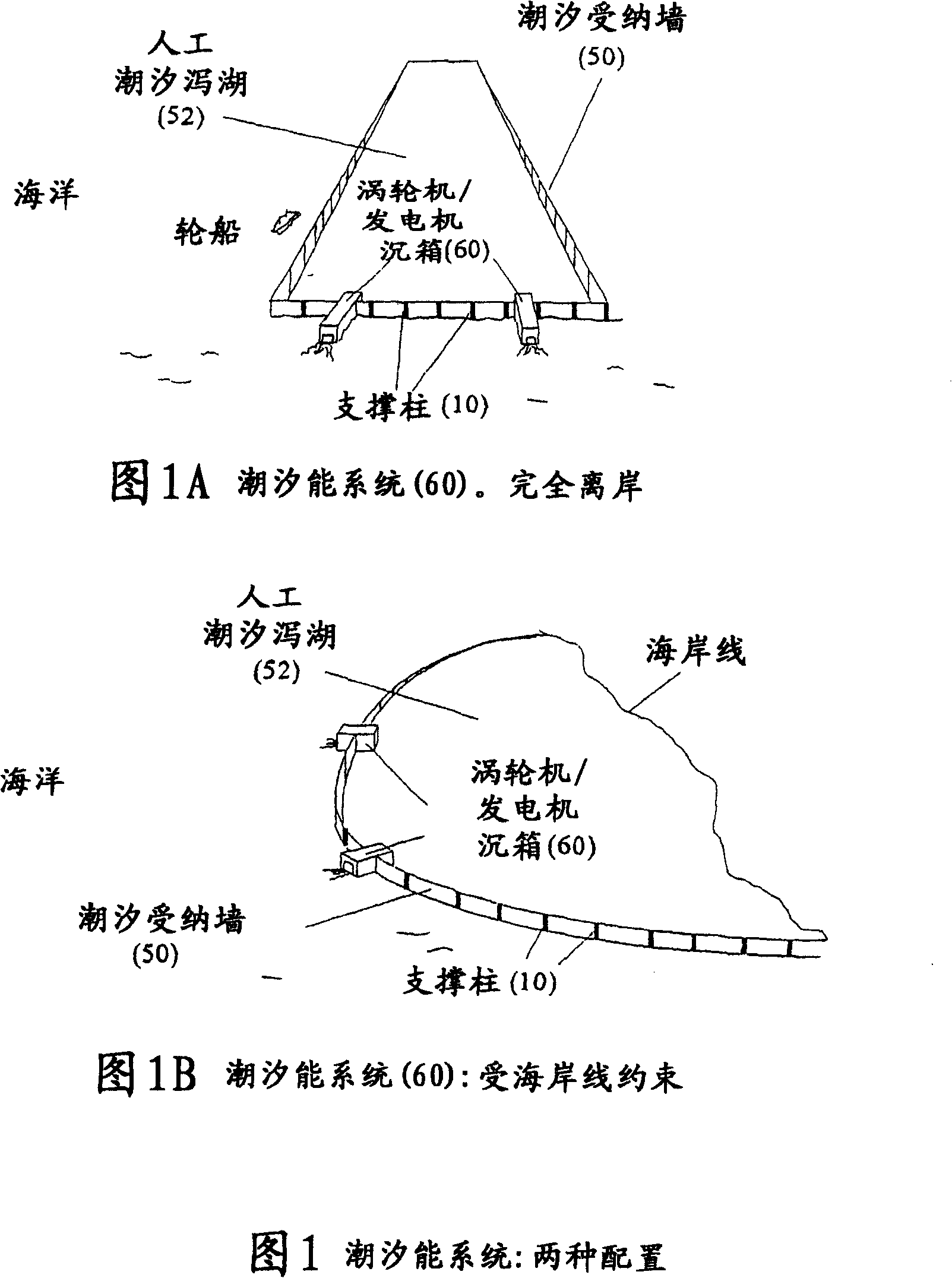
[0099]Figure 1 depicts two configurations of a basic version of a tidal energy system (70). The tidal receiving wall (50) encloses the inner water body, namely the artificial tidal lagoon (52). A turbine / generator caisson (60) is contained within the tidal receiving wall (50). The tidal receiving wall is assembled with tidal receiving wall sections (36) (Fig. 2).

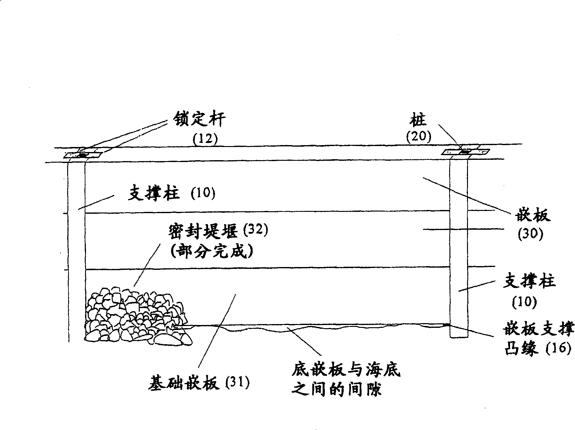
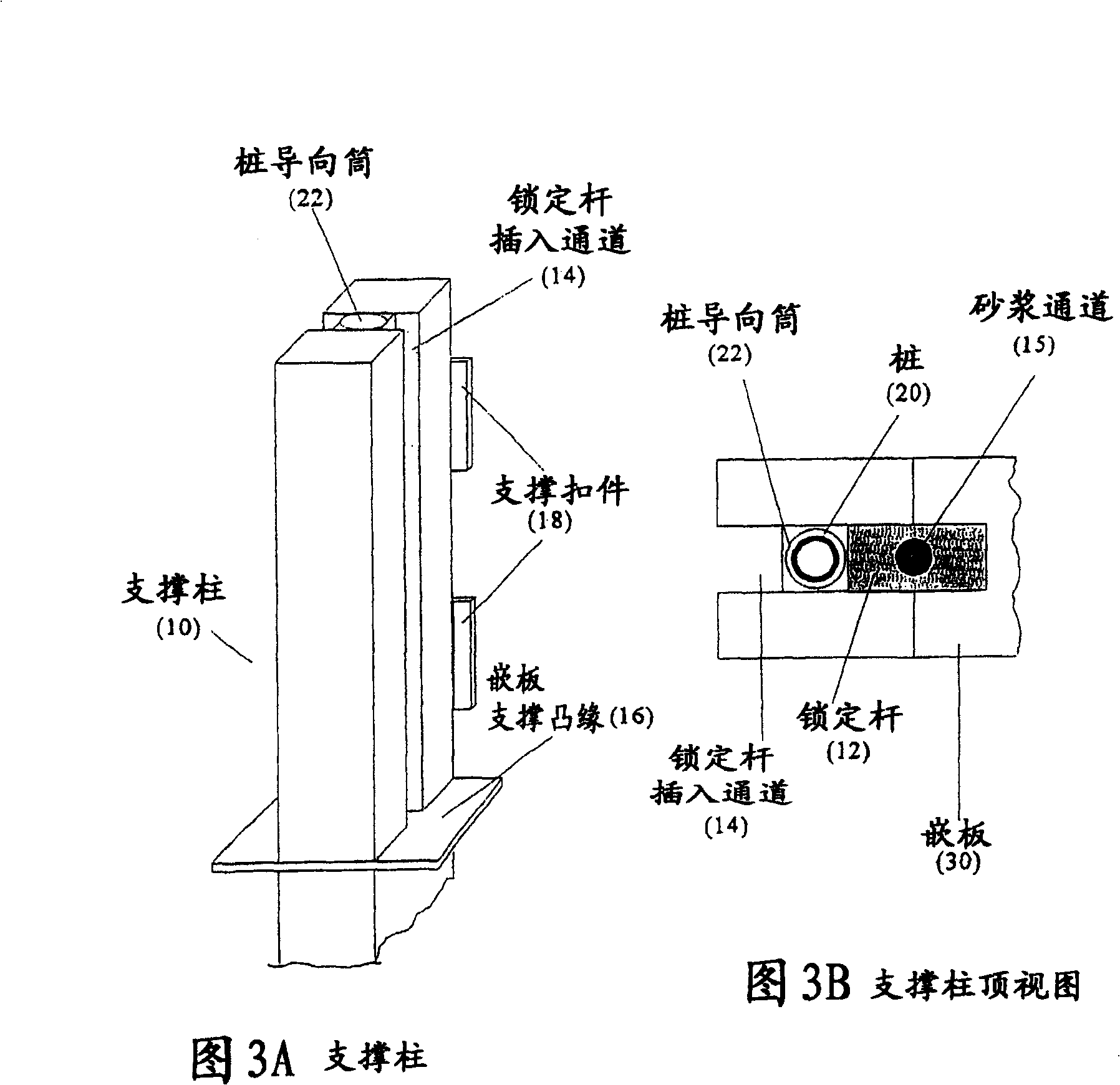
[0100] Each tidal receiving wall section (Fig. 2) consists of four basic components: (i) support columns (10), which form the frame and connect the tidal receiving wall sections together, (ii) piles (20), It secures the support columns to the seabed, (iii) the panels (30), which separate the artificial tidal lagoon from the surrounding ocean, and (iv) the locking rods (12), which secure the panels to the support columns.

[0101] The support columns (10) form the frame of the tidal receiving wall (Fig. 1...


PUM


Abstract

The tidal energy system is a structure that can absorb energy from the potential and kinetic energy of the tide, as well as from ocean waves and land winds. Its components operate synergistically in multiple capacities, drawing energy from these sources, enabling the tidal energy system to operate as a whole. Tidal energy systems are constructed so that they can operate integrated with electrolyzer and fuel cell technologies to produce instant power, thereby eliminating the pulsating nature of tidal power. The present tidal energy system can also produce hydrogen as an end product.

Description

technical field [0001] This invention relates to the generation of electricity from ocean tides, ocean waves, and land winds, and the integration of hydrogen technology with tidal energy. Background technique [0002] The general principles underlying the generation of electricity from the tides are straightforward. For conventional tidal power stations, the dam is built at the mouth of the harbor. Dams function as dams, separating the waters of the harbor from the waters of the sea. Dams use the ebb and flow of tides to create a water level difference between the ocean and the harbour. Electricity is generated by passing water through a turbine / generator set into the dam. [0003] A barrage consists of three components: (1) a turbine / generator set below low water mark, (2) a gated channel to control the flow of water between the ocean and the harbor, and (3) an inactive segment, the only The function is to separate the ocean from the harbor. There are two modes of elec...

Claims


Application Information

Patent Timeline
Patent Type & Authority Patents(China)
IPC IPC(8): H02P9/04F03B13/10
CPCF03B13/268Y02E10/38Y02E10/32Y02E10/28F03B13/142E02B9/08F03B13/264Y02E10/22F05B2250/183F03B13/10Y02E10/30F03B13/12F03B13/26H02P9/04
Inventor 拉米兹·阿提亚
Owner 拉米兹·阿提亚
Learn More