Power Generation System and Power Generation Method

a power generation system and power generation method technology, applied in the direction of machines/engines, mechanical equipment, circuit arrangements, etc., can solve the problems of difficult to keep a constant frequency of the system, the power generation output to be obtained is not constant, and the inability to control natural conditions, so as to enhance the tracking performance enhance the reliability of the power generation equipment.

Active Publication Date: 2017-05-25
HITACHI LTD
View PDF9 Cites 25 Cited by
  • Summary
  • Abstract
  • Description
  • Claims
  • Application Information

AI Technical Summary

Benefits of technology

[0015]It is possible to enhance the tracking performance of the power generation equipment with respect to the load variation and to enhance the reliability of the power generation equipment.

Problems solved by technology

However, it is not possible to control natural conditions, and power generation output to be obtained is not constant but varies.
If such a power supply is connected to a system, the system becomes unstable, and there is a risk that it is difficult to keep a constant frequency of the system.

Method used


Image

  • Power Generation System and Power Generation Method
  • Power Generation System and Power Generation Method
  • Power Generation System and Power Generation Method

Examples


first embodiment

[0036]A two-shaft gas turbine to which the present invention is applied and one including the two-shaft gas turbine will be described in the present embodiment.

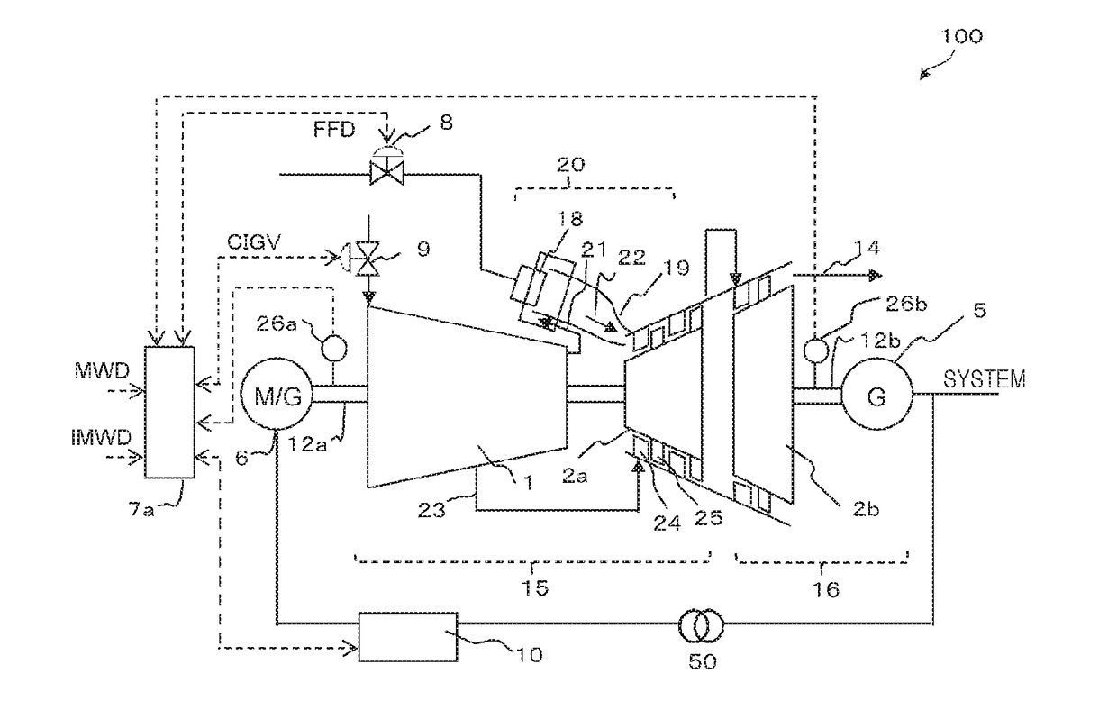
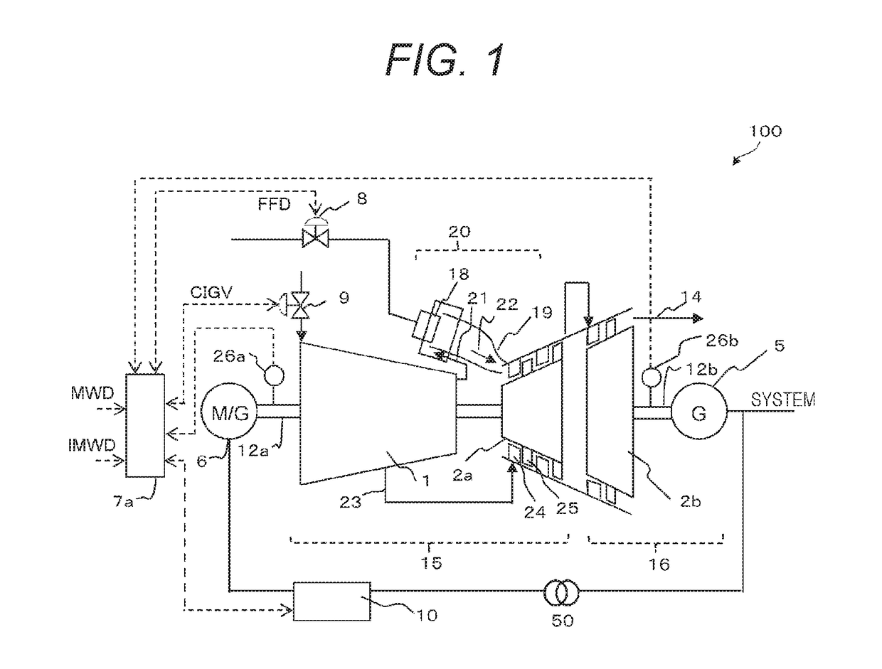
[0037]FIG. 1 illustrates a two-shaft gas turbine power generation apparatus 100 according to an embodiment of the present invention.

[0038]The two-shaft gas turbine power generation apparatus 100 includes a gas generator 15, a power turbine 16, a GT (Gas Turbine) control apparatus (controller) 7a, and a frequency converter 10.

[0039]The power turbine 16 includes a low pressure turbine 2b, a low pressure turbine shaft 12b which is a shaft of the low pressure turbine 2b, and a power generator 5 which converts a rotational force of the low pressure turbine shaft 12b into power. In the gas turbine for power generation, the power generator 5 is driven at substantially constant low pressure turbine rotational speed by rotation of the power turbine 16 at substantially constant low pressure turbine rotational speed in order to make a f...

second embodiment

[0148]In the present embodiment, a power generation system which uses solar power generation as renewable energy will be described. In the present embodiment, a difference from the first embodiment will be described.

[0149]FIG. 16 illustrates a configuration of the power generation system of a second embodiment.

[0150]When compared with the power generation system of the first embodiment, the power generation system of the present embodiment includes a solar power generation apparatus 1000 instead of the wind power generation apparatus 30 as a renewable energy generation apparatus. The solar power generation apparatus 1000 is obtained by combining a plurality of solar panels 1100. The control apparatus 200 of the present embodiment includes a model calculation unit 401 which predicts output of the solar power generation apparatus 1000 using a solar power generation model, which is a model of the solar power generation apparatus 1000, instead of the model calculation unit 400 and sets ...

third embodiment

[0156]In addition, although the two-shaft gas turbine power generation apparatus 100 has been used in each of the first and second embodiments, the present invention can be also applied to a combined cycle plant. In the present embodiment, a difference from the first embodiment will be described.

[0157]FIG. 18 illustrates a configuration of a power generation system of a third embodiment.

[0158]When compared with the power generation system of the first embodiment, the power generation system of the present embodiment includes a steam turbine power generation apparatus 710 instead of the wind power generation apparatus 30. A power generation apparatus obtained by combining the two-shaft gas turbine power generation apparatus 100 and the steam turbine power generation apparatus 710 will be referred to as a combined cycle plant 700. The steam turbine power generation apparatus 710 includes an exhaust heat recovery boiler 720, a steam turbine 730, a power generator 740, a condenser 750, ...


PUM


Abstract

In order to enhance the tracking performance of power generation equipment with respect to a load variation and increase the reliability of the power generation equipment, a dynamic characteristic model simulating the dynamic characteristics of a multi-shaft gas turbine is used to calculate an output prediction value of a first power generator in a case where a combustor is controlled so as to match the output of the first power generator to an output target value; on the basis of the output target value and the output prediction value of the first power generator, a first power generator output instruction value as an instruction value for the output from the first power generator to a power system and a second power generator output instruction value as an instruction value for the output from a second power generator to the power system are calculated; and the combustor is controlled on the basis of the first power generator output instruction value and a frequency convertor is controlled on the basis of the second power generator output instruction value.

Description

TECHNICAL FIELD[0001]The present invention relates to a power generation system.BACKGROUND ART[0002]A thermal power plant is a power generation apparatus that generates power by driving a power generation apparatus using combustion heat taken out through combustion mainly of fossil fuel, and various types of power generation apparatuses are present depending on combinations of fuel and the power generation apparatus. Examples of such apparatuses include a steam turbine power generation apparatus that generates power by burning coal or heavy oil in a boiler and generating steam using combustion heat therefrom to drive a steam turbine, a gas turbine power generation apparatus that generates power by compressing atmospheric air with a compressor, mixing and burning the compressed air with fuel in a combustor, and driving a gas turbine using combustion air therefrom, or a combined cycle power generation apparatus that generates steam in an exhaust heat recovery boiler using an exhaust g...

Claims


Application Information

Patent Timeline
Patent Type & Authority Applications(United States)
IPC IPC(8): F02C9/20F01K11/02F02C7/36F02C6/18F02C7/057
CPCF02C9/20F02C6/18F02C7/057F02C7/36F05D2270/061F05D2220/32F05D2220/72F05D2220/76F01K11/02F02C6/00F02C9/00F05D2270/44Y02E20/16Y04S10/123Y04S10/40F03D7/0284F03D9/00F01D15/10F01K13/02F02C3/10H02J3/00F05B2220/704F05D2270/71H02J2203/20H02J13/00001H02J2300/28H02J2300/24H02J3/381Y02E10/56Y02E10/76Y02E40/70Y02E60/00Y04S40/20H02J3/46
Inventor KUSUMI, NAOHIROHINO, NORIAKITHET, AUNG KOSHIRAISHI, TOMOFUMIYOSHIMURA, MASATOSHI
Owner HITACHI LTD
Why Eureka
Try Eureka