Switched reluctance generator current transformer topology and control method thereof

A technology of switched reluctance and generator, which is applied in the direction of synchronous generator control and generator control through magnetic field changes. It can solve the problems of frequent control, frequent charging and discharging of internal electrical components, etc., to save costs and reduce manual participation. , High stability effect

Inactive Publication Date: 2017-08-18
CHINA JILIANG UNIV
View PDF7 Cites 23 Cited by
  • Summary
  • Abstract
  • Description
  • Claims
  • Application Information

AI Technical Summary

Problems solved by technology

[0007] Although the switched reluctance generator has strong fault tolerance, that is, if a certain phase winding does not participate in power generation for a short time, it will not affect the overall power generat

Method used


Image

  • Switched reluctance generator current transformer topology and control method thereof
  • Switched reluctance generator current transformer topology and control method thereof
  • Switched reluctance generator current transformer topology and control method thereof

Examples


Embodiment Construction

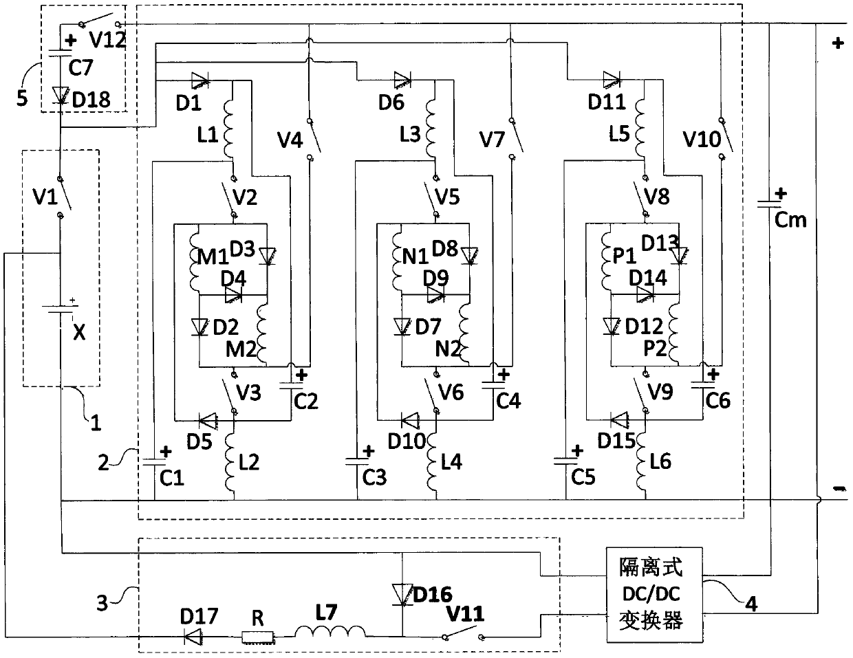
[0048] A switched reluctance generator converter topology, consisting of an excitation power source 1, a converter main circuit 2, a charging circuit 3, a bus capacitor Cm, an isolated DC / DC converter 4, and a discharge circuit 5, and both ends of the output of the excitation power source 1 Connect the input ends of the inverter main circuit 2, the input ends of the excitation power supply 1 are connected to the output ends of the charging circuit 3, the output ends of the inverter main circuit 2 are connected across the bus capacitor Cm, and are connected to the isolated DC / DC converter The two ends of the input of 4 are connected, the two ends of the output of the isolated DC / DC converter 4 are connected to the two ends of the input of the charging circuit 3, the positive end of the two ends of the discharge circuit 5 is connected to the positive end of the output of the inverter main circuit 2, and the discharge circuit The negative terminal of 5 is connected to the input po...


PUM


Abstract

The invention relates to a switched reluctance generator current transformer topology and a control method thereof. The topology comprises an excitation power source, a main current transformer circuit, a bus capacitor, an isolated DC/DC converter and a discharging circuit, wherein the excitation power source supplies electric excitation for the main current transformer circuit. Through the main current transformer circuit structure and the control method thereof, the excitation effect can be enhanced, the charging circuit works when a storage cell of the excitation power source needs charging and enhancing power output capability and protection, power generation initial current capability is protected and properly enhanced through controlling the discharging circuit, whole system intelligence, high efficiency and high benefits are realized, a special excitation initiating power source is omitted, and the topology and the method are suitable for application in the small and medium switched reluctance generator current transformer field.

Description

technical field [0001] The invention relates to the field of switched reluctance motors, in particular to a converter circuit topology system of a switched reluctance generator and a control method thereof. Background technique [0002] The use of switched reluctance generators to generate electricity is a new type of electricity generation. [0003] The power generation conversion system of the switched reluctance generator is the foundation and key of the switched reluctance generator system, which is related to the efficiency, benefit and reliability of power generation. [0004] According to the working principle of the switched reluctance generator, its work is divided into two stages: excitation and power generation. First, the external power supply supplies power to the windings for excitation energy storage, and then under the action of the reverse torque of the operation, the magnetic energy storage is freewheeling and released, which is the output of power generati...

Claims


Application Information

Patent Timeline
IPC IPC(8): H02P9/38H02P103/20
CPCH02P9/38H02P2103/20
Inventor 孙冠群
Owner CHINA JILIANG UNIV
Why Eureka
Try Eureka