
Piezoelectric energy harvester for recovering pressure pulsation energy of liquid

An energy recovery, piezoelectric energy capture technology, applied in the direction of fluid pressure actuation devices, fluid pressure actuation system components, piezoelectric effect/electrostrictive or magnetostrictive motors, etc., can solve the pulsation suppression effect and general problems such as poor performance, fluid pressure pulsation energy waste, etc., to achieve the effects of high energy conversion efficiency and reliability, strong power generation capacity, and simple system structure

Active Publication Date: 2012-09-12
ZHEJIANG NORMAL UNIVERSITY +2
View PDF4 Cites 23 Cited by
  • Summary
  • Abstract
  • Description
  • Claims
  • Application Information

AI Technical Summary

Problems solved by technology

The so-called passive control realizes the suppression of fluid pressure pulsation by dissipating energy. Compared with the active method, its system structure is simple, the cost is low, and the technology is relatively mature, but the pulsation suppression effect and versatility are poor, and the fluid pressure pulsation energy is wasted
It can be seen that the existing active and passive fluid pressure pulsation control technologies have certain limitations and deficiencies. Hydraulic pressure pulsation suppression and elimination technology is urgently needed in many fields. In order to achieve this goal, the hydraulic pulsation energy must be effectively recovered

Method used


Image

  • Piezoelectric energy harvester for recovering pressure pulsation energy of liquid
  • Piezoelectric energy harvester for recovering pressure pulsation energy of liquid
  • Piezoelectric energy harvester for recovering pressure pulsation energy of liquid

Examples


Embodiment Construction

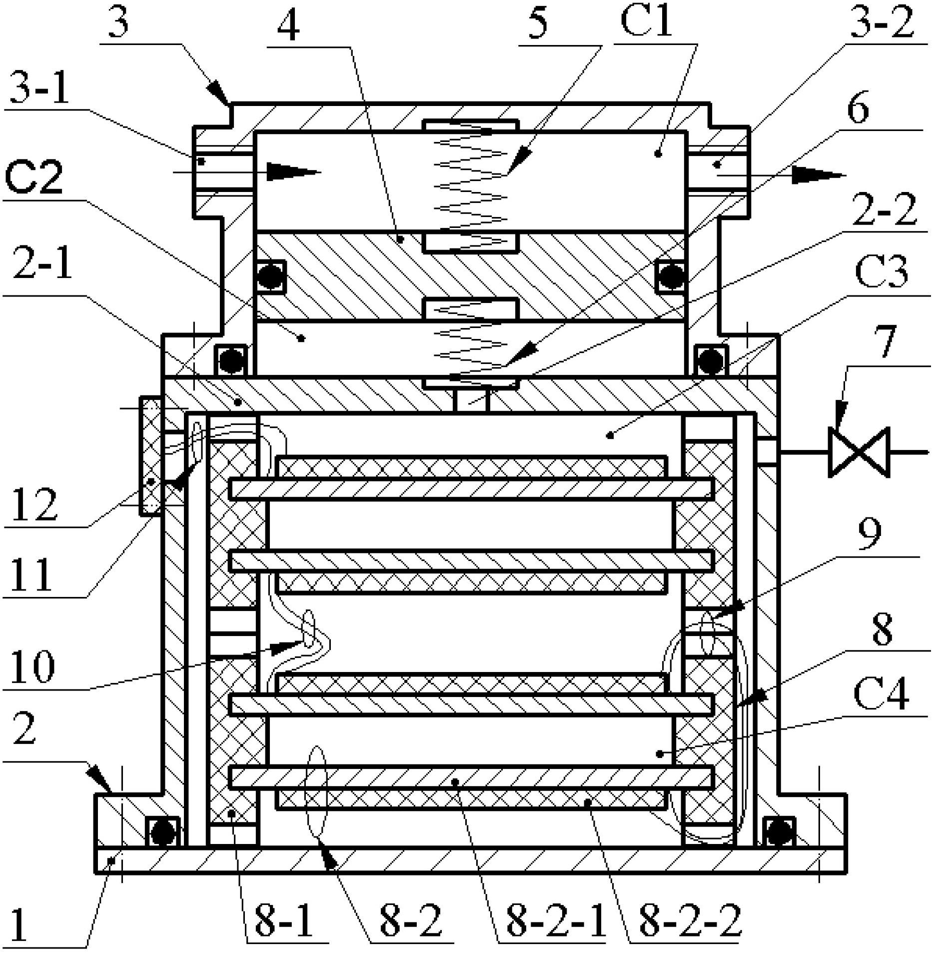
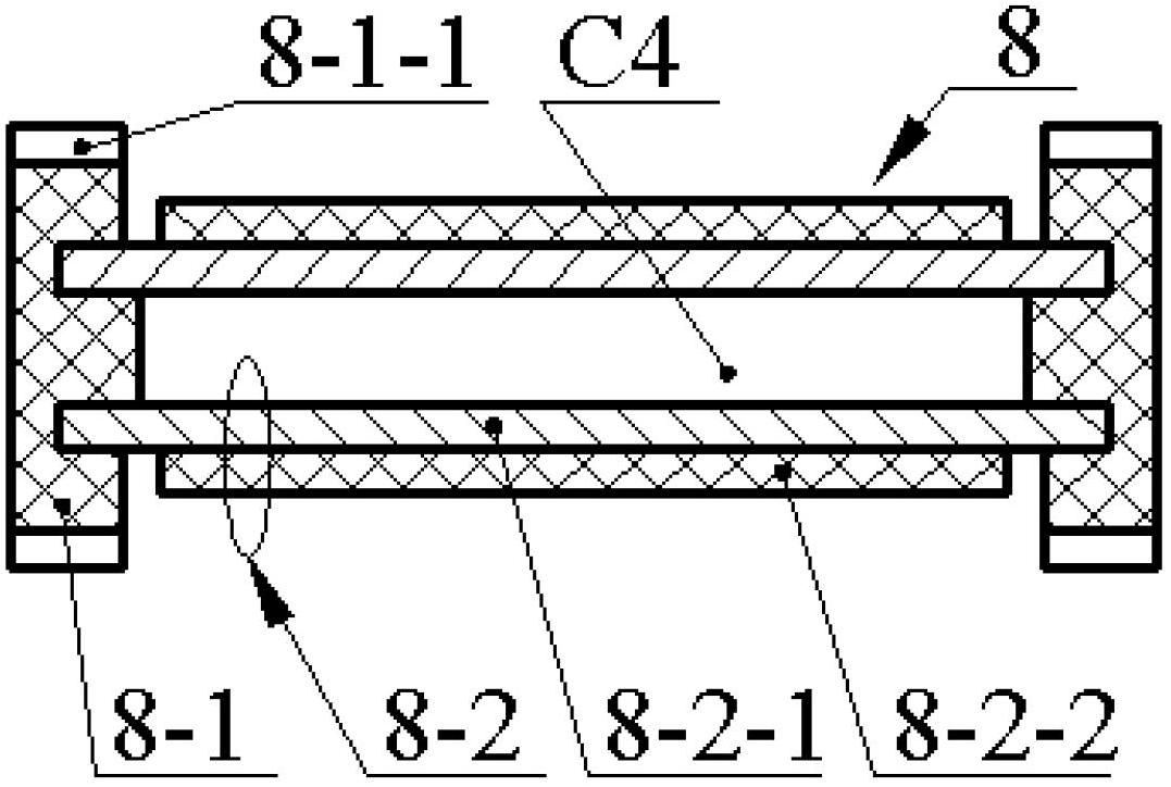
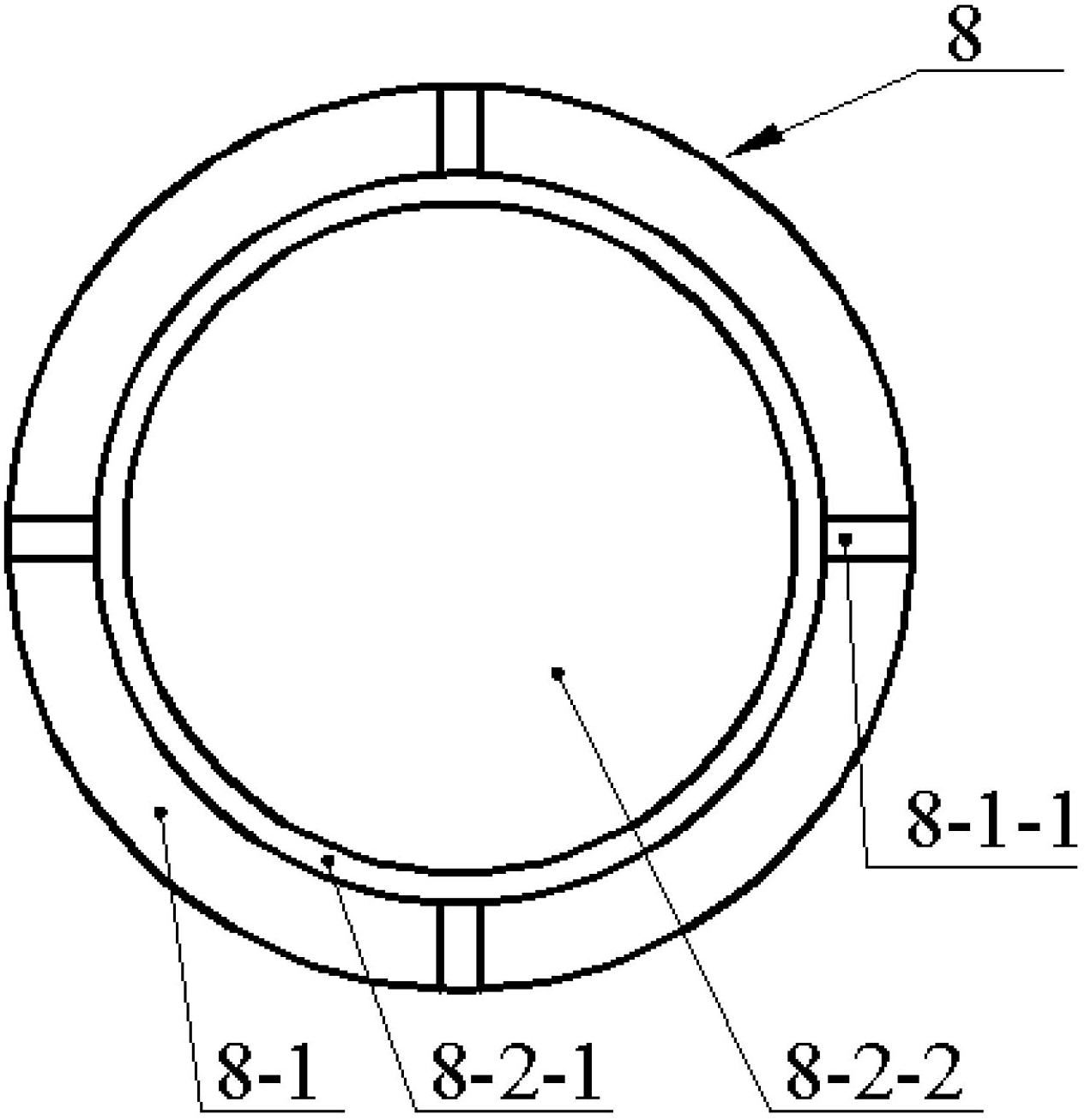
[0014] Such as figure 1 As shown, the first cylinder body 2 is fixed on the base 1 by screws, the circuit board 12 and the shut-off valve 7 are respectively fixed on the side wall of the first cylinder body 2 by screws and pipelines, and the second cylinder body 3 is fixed on the side wall of the first cylinder body by screws. On a cylinder 2; the piston 4 is crimped inside the second cylinder 3 through the first spring 5 and the second spring 6, and divides the second cylinder 3 into a first chamber C1 and a second chamber C2; The side wall of the first chamber C1 is provided with a fluid inlet 3-1 and an outlet 3-2, and the second chamber C2 is connected to the first cylinder chamber through the through hole 2-2 at the upper end 2-1 of the first cylinder 2. C3 is connected; 1-50 piezoelectric transducers 8 are crimped in the first cylinder cavity C3, and the piezoelectric transducers 8 are composed of a ring bracket 8-1 and a pair of piezoelectric vibrators 8-2, so The annu...


PUM


Abstract

The invention relates to a piezoelectric energy harvester for recovering pressure pulsation energy of liquid, belonging to the technical fields of new energy power generation and fluid pressure pulsation suppression. A first cylinder body is fixed on a base through screws, a circuit board and a stop valve are respectively fixed on the side wall of the first cylinder body through a screw and a pipeline, and a second cylinder body is fixed on the first cylinder body through the screws; a piston is pressed and connected in the second cylinder body through a first spring and a second spring and is used for dividing the second cylinder body into a first cavity and a second cavity; a fluid inlet and a fluid outlet are arranged on the side wall of the first cavity, and the second cavity passes through a through hole at the upper end of the first cylinder body and is communicated with a cavity of the first cylinder body; and 1-50 piezoelectric transducers are pressed and connected in the cavity of the first cylinder body. The piezoelectric energy harvester has the advantages that a liquid medium is utilized for transferring motion and energy so as to enable multiple piezoelectric vibrators to generate power synchronously and avoid damages due to mutual contact when the deformation of the piezoelectric vibrators is too large. Therefore, the system has the advantages of simple structure, strong power generation capacity and higher reliability.

Description

technical field [0001] The invention belongs to the field of new energy power generation technology and fluid pressure pulsation suppression technology, and in particular relates to a piezoelectric wafer type energy harvester, which is used for hydraulic fluid pulsation energy recovery and power generation and its pulsation suppression. Background technique [0002] The research on the use of piezoelectric ceramic materials to recycle environmental energy for power generation has become a hot spot at home and abroad for many years. The successful development and utilization of piezoelectric power generation devices can not only solve the problem of waste batteries polluting the environment and the waste of resources caused by battery production, but also solve the real-time power supply in the fields of portable electronic products, remote sensor monitoring, and vibration control. question. According to different forms of environmental energy and application purposes, vario...

Claims


Application Information

Patent Timeline
Patent Type & Authority Applications(China)
IPC IPC(8): H02N2/18F15B21/14
Inventor 阚君武杨振宇王淑云曾平程光明安智琪
Owner ZHEJIANG NORMAL UNIVERSITY
Learn More