
Printer

a printing machine and printing plate technology, applied in the field of printing machines, can solve the problems of difficult security of the desirable movable area of the communication unit, and achieve the effect of not affecting the communication

Pending Publication Date: 2022-07-21
SATO HLDG CORP
View PDF2 Cites 0 Cited by
  • Summary
  • Abstract
  • Description
  • Claims
  • Application Information

AI Technical Summary

Benefits of technology

The invention aims to secure the movable area of a communication unit without affecting communications. This is achieved by providing a light guiding member that directs detection light emitted from a light emitter to the printing medium. The light emitter can be positioned more freely, allowing it to be placed without interfering with the movement of the communication unit. Therefore, the movable area of the communication unit can be secured without hindering communications.

Problems solved by technology

Thus, there has been a problem in that a desirable movable area of the communication unit is difficult to secure.

Method used


Image

  • Printer
  • Printer
  • Printer

Examples


first embodiment

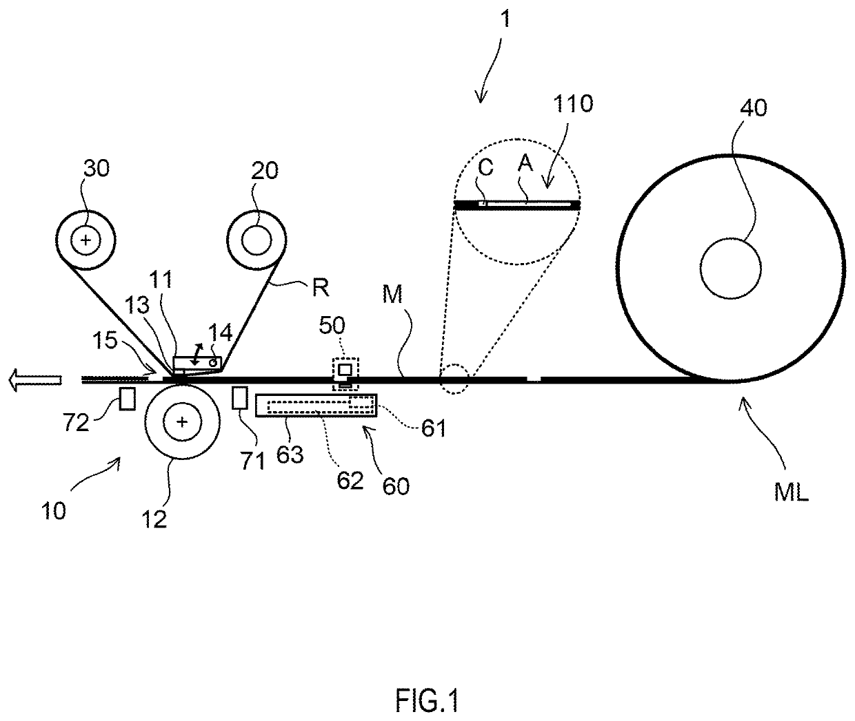
[0017]A printer 1 according to a first embodiment of the present invention will be described in detail with reference to the attached drawings. FIG. 1 is a schematic view illustrating a configuration of the printer 1 according to the first embodiment of the present invention.

[0018]The printer 1 is of a thermal transfer type, and performs printing by transferring ink on an ink ribbon R onto a printing medium M by heating the ink ribbon R. The printing medium M is formed as a continuous body ML that has a strip shaped mount on which a plurality of labels are sequentially and detachably attached at a predetermined pitch and is rolled into a roll shape, for example.

[0019]The printing medium M incorporates a Radio Frequency Identification (RFID) 110. Note that the printer 1 can also perform printing on a printing medium not having the RFID 110. This RFID is an RFID inlet including an IC chip C and an antenna A.

[0020]The printer 1 prints, on a printing region of the printing medium M, var...

second embodiment

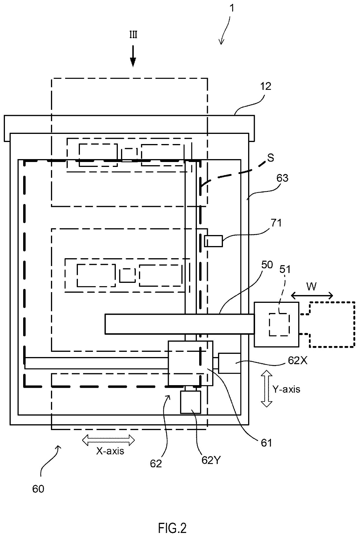
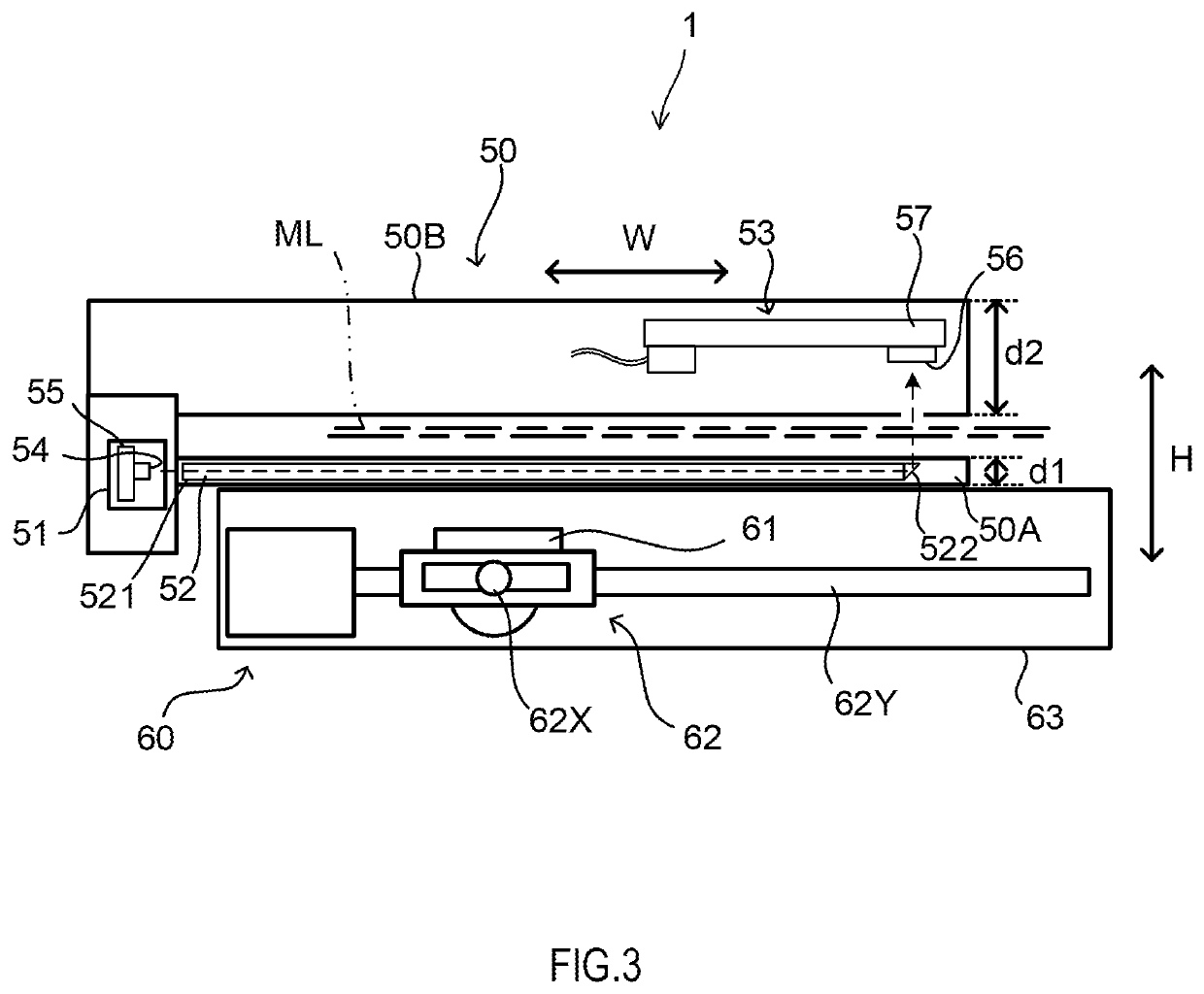
[0070]A printer 2 according to a second embodiment of the present invention will be described below with reference to the attached drawings. FIG. 4 is a plan view of a detection unit 50 and a communication unit 60 according to the printer 2. FIG. 5 is a side view as viewed in an arrow V in FIG. 4. In the printer 2 illustrated in FIG. 4 and FIG. 5, the components having the same functions as those in the printer 1 illustrated in FIG. 2 and FIG. 3 will be denoted by the same reference numerals and the detailed description thereof will be omitted.

[0071]The printer 2 further includes a frame 80 arranged outside a predetermined area S in the width direction W of the printing medium M.

[0072]The frame 80 is a member for shielding electromagnetic noise radiated from the light emitter substrate 55. In the present embodiment, the frame 80 is a part of the printer 2. The frame 80 may also serve as a supporting member that supports the upper side unit 50B from the communication unit 60 side.

[00...


PUM


Abstract

This printer performs printing on a print medium having an RFID, and comprises: a communication unit which has a communication part movably provided in a predetermined area along the transport surface of the print medium, and communicates with an IC chip of the RFID; and a detection unit which detects the print medium by means of detection light. The detection unit includes: a light emitting part that emits detection light; a light guide member that guides the detection light emitted from the light emitting part to the print medium; and a light receiving part that receives the detection light via the print medium.

Description

TECHNICAL FIELD[0001]The present invention relates to a printer.BACKGROUND ART[0002]JP6403966B discloses a printer that performs printing on a label attached temporally to one surface of a label continuous body, and has a transmissive sensor provided on an upstream side of a printing unit. The transmissive sensor includes a light emitting element that emits detection light for detecting the label, and a light receiving element that is arranged to face the light emitting element with the label interposed in between and receives the detection light.[0003]In the printer described above, the transmissive sensor is configured to be a sensor unit having the light emitting element and the light receiving element respectively provided to an upper sensor attachment holder and a lower sensor attachment holder. The sensor unit is arranged to make the label continuous body inserted between the upper sensor attachment holder and the lower sensor attachment holder.[0004]With this configuration, t...

Claims


Application Information

Patent Timeline
Patent Type & Authority Applications(United States)
IPC IPC(8): B41J11/00G06K7/10B41J35/00
CPCB41J11/0095B41J35/00G06K7/10297G06K1/22G06K7/10128B41J3/4075
Inventor KOKUTA, HIROSHI
Owner SATO HLDG CORP
Learn More