Tag device, antenna, and portable card

a portable card and antenna technology, applied in the direction of shielding material radiating elements, instruments, and semiconductor/solid-state device details, etc., can solve the problems of sharp weakening of magnetic field, affecting communication quality, and affecting communication quality, so as to achieve high-quality radio communication and hinder communication

Inactive Publication Date: 2011-02-01
FUJITSU LTD
View PDF14 Cites 3 Cited by
  • Summary
  • Abstract
  • Description
  • Claims
  • Application Information

AI Technical Summary

Benefits of technology

[0040]The present invention was made under the background circumstances described above. An object of the present invention is to provide a tag device for performing high-quality radio communication without radio wave radiation or receiving characteristics being deteriorated near a person's body and without hindering communication by another IC tag.
[0041]Another object of the present invention is to provide an antenna for performing high-quality radio communication without radio wave radiation or receiving characteristics being deteriorated near a person's body and without hindering communication by another IC tag.
[0042]Still another object of the present invention is to provide a portable card for performing high-quality radio communication without radio wave radiation or receiving characteristics being deteriorated near a person's body and without hindering communication by another IC tag.

Problems solved by technology

When the IC tag using the 13.56 MHz frequency band is distant from the reader / writer, the magnetic field weakens sharply and electric power cannot be secured.
Therefore, the length of the dipole antenna is about 11 m. This length is not practical.
The disadvantage of IC tags using the 13.56 MHz frequency band is that communication distance cannot be lengthened.
With IC tags using a UHF band, on the other hand, communication distance is long and the disadvantage of IC tags using the 2.45 GMHz frequency band does not exist.
However, when a card in which an IC tag using a UHF band and including the above folded dipole antenna fdp is embedded is near a person's body, radio waves radiated are intercepted or absorbed by the person's body.
As a result, the radio wave radiation and receiving characteristics deteriorate.
This means that the radio waves v are not fully radiated.
As a result, the radio wave radiation and receiving characteristics deteriorate.
As a result, the IC tag using the 13.56 MHz frequency band does not function and communication cannot be performed.

Method used


Image

  • Tag device, antenna, and portable card
  • Tag device, antenna, and portable card
  • Tag device, antenna, and portable card

Examples


Embodiment Construction

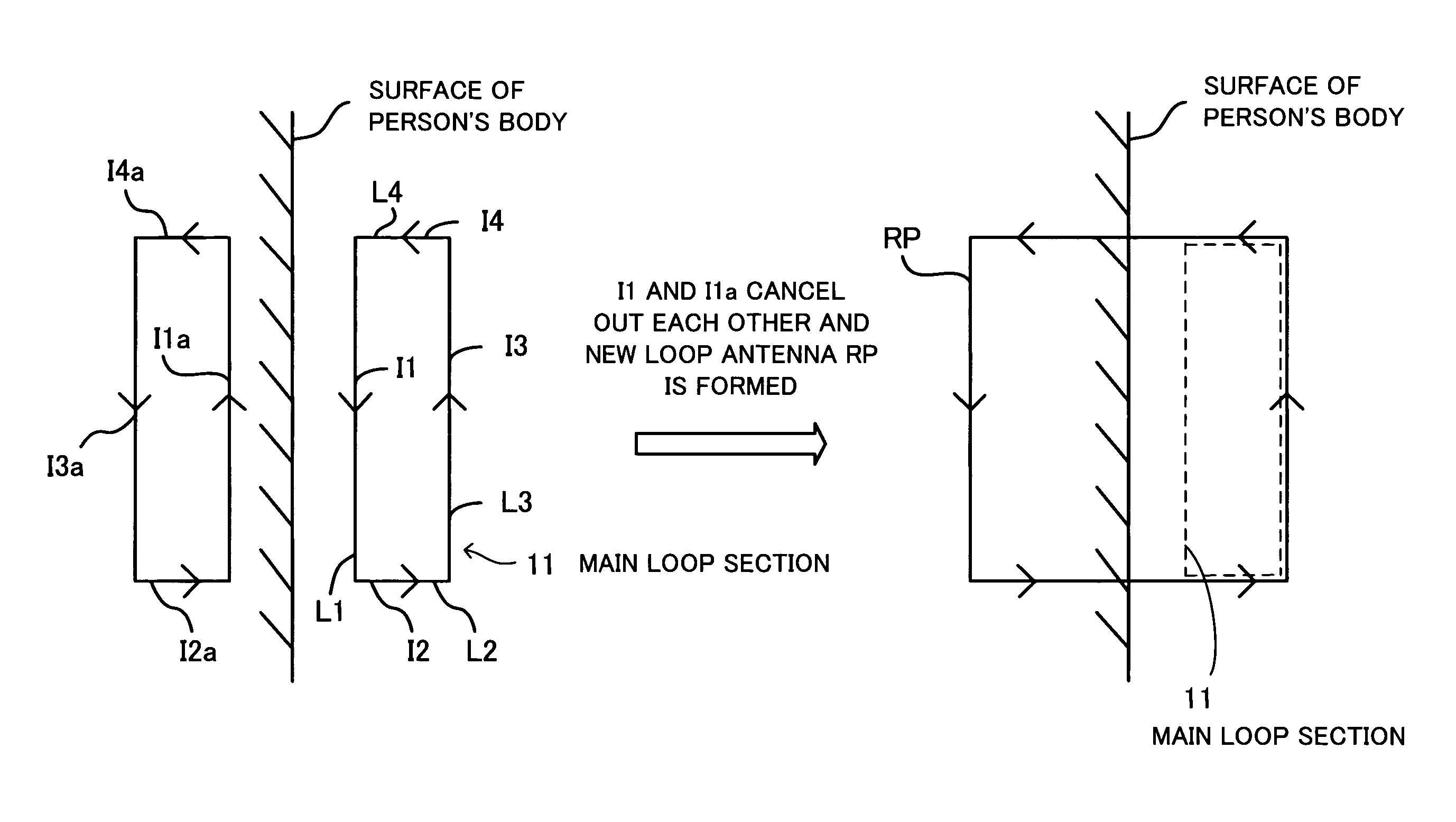
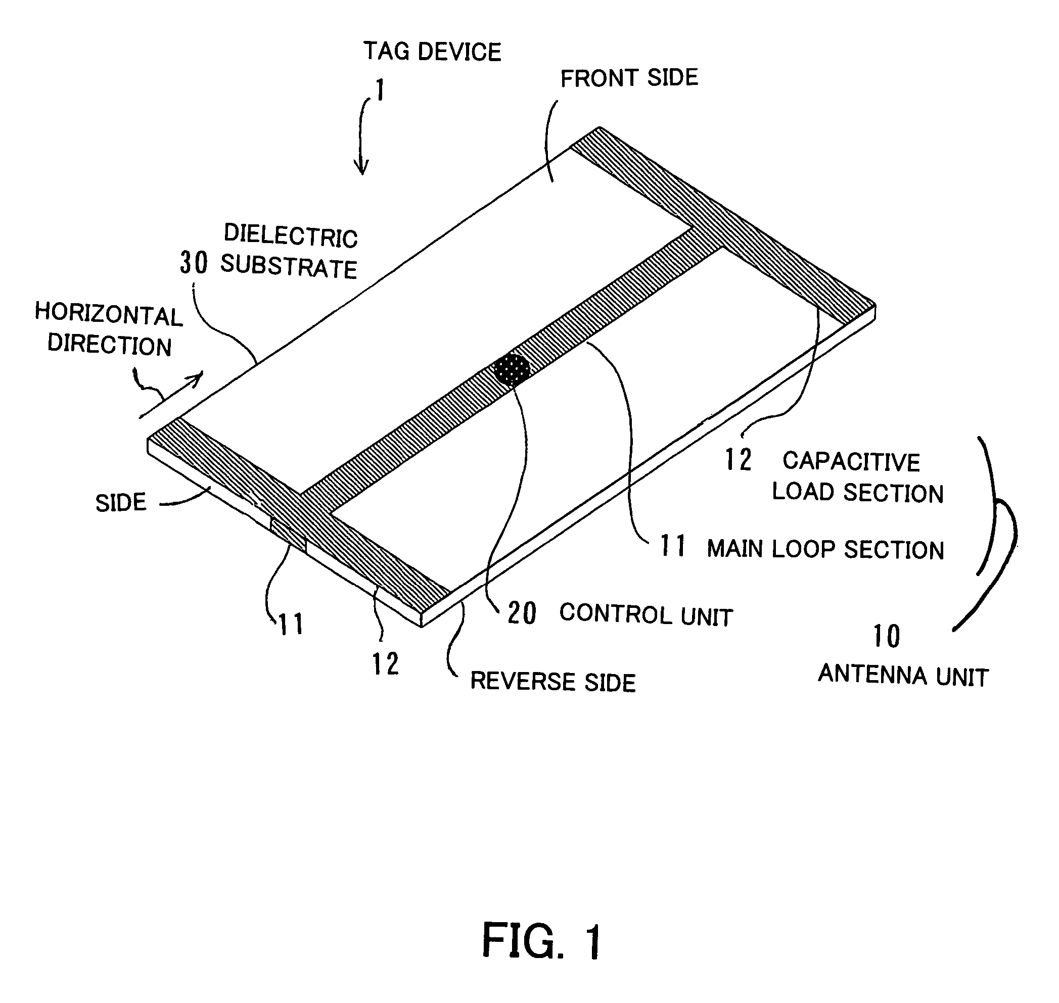
[0061]Embodiments of the present invention will now be described with reference to the drawings. FIG. 1 is a view for describing the principles underlying a tag device. A tag device 1 comprises an antenna unit 10, a control unit 20, and a dielectric substrate 30. The tag device 1 is used for performing radio communication and is used as, for example, an RFID IC tag using a UHF band.

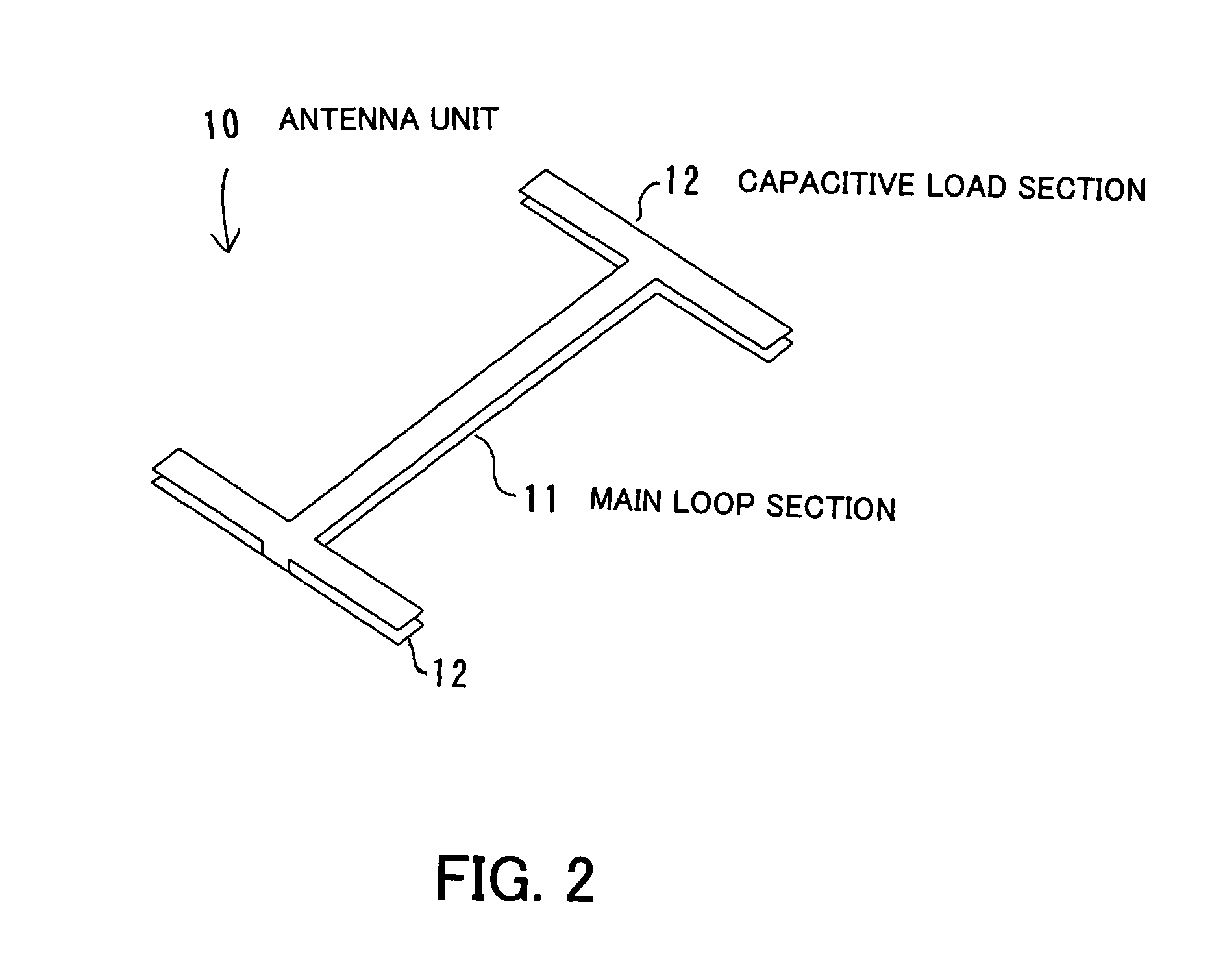
[0062]The antenna unit 10 includes a main loop section 11 and capacitive load sections 12. The main loop section 11 is a loop-like metal foil mounted on the surface of the dielectric substrate 30 and sends and receives radio waves. (That is to say, the main loop section 11 fulfills a chief part of an antenna function.) Each of the capacitive load sections 12 is a metal foil connected to the main loop section 11 and has a load corresponding to a capacitance component.

[0063]As shown in FIG. 1, the main loop section 11 of the antenna unit 10 has the shape of a long thin loop and its area is smaller than the ...


PUM


Abstract

A tag device that performs high-quality radio communication without radio wave radiation or receiving characteristics being deteriorated near a person's body and without hindering communication by another IC tag. A main loop section sends and receives radio waves. The main loop section is a metal foil and has the shape of a long thin loop. The area of the main loop section is smaller than the area of a dielectric substrate. The main loop section covers part of surfaces of the dielectric substrate and part of sides of the dielectric substrate so as to put the dielectric substrate inside the loop. The main loop section is mounted in a horizontal direction of the dielectric substrate. Each of capacitive load sections is a metal foil and has a load corresponding to a capacitance component. The capacitive load sections are located at both end portions of the main loop section which covers part of the front side of the dielectric substrate and are located at both end portions of the main loop section which covers part of the reverse side of the dielectric substrate. A control unit is connected to the main loop section and controls information via the radio waves.

Description

[0001]This application is a continuing application, filed under 35 U.S.C. §111(a), of International Application PCT / JP2005 / 000091, filed Jan. 7, 2005.BACKGROUND OF THE INVENTION[0002]1. Field of the Invention[0003]This invention relates to a tag device, an antenna, and a portable card and, more particularly, to a tag device for performing radio communication, an antenna for radiating and receiving radio waves, and a portable card for performing radio communication.[0004]2. Description of the Related Art[0005]In recent years attention has been riveted on an automatic identification technique called radio frequency-identification (RFID). The RFID is a kind of radio communication system by which an object on which an IC tag is put is automatically identified by radio on a noncontact basis. With the RFID, IC tags can be put on all objects and be connected to networks. Accordingly, the development of the RFID has advanced swiftly as a technique which is effective in building the next gen...

Claims


Application Information

Patent Timeline
Patent Type & Authority Patents(United States)
IPC IPC(8): H01Q7/00H01Q11/12G06K19/00
CPCG06K19/07771H01Q1/2225
Inventor YAMAGAJO, TAKASHIMANIWA, TORUKAI, MANABU
Owner FUJITSU LTD
Why Eureka
Try Eureka