Turning insert for metal cutting

a technology for turning inserts and metal cutting, which is applied in the direction of cutting inserts, turning machines, metal-working apparatuses, etc., and can solve problems such as becoming more fragil

Pending Publication Date: 2022-07-28
SANDVIK COROMANT
View PDF0 Cites 0 Cited by
  • Summary
  • Abstract
  • Description
  • Claims
  • Application Information

AI Technical Summary

Problems solved by technology

The first protrusions bends the chip so it becomes more fragile.

Method used


Image

  • Turning insert for metal cutting
  • Turning insert for metal cutting
  • Turning insert for metal cutting

Examples


Embodiment Construction

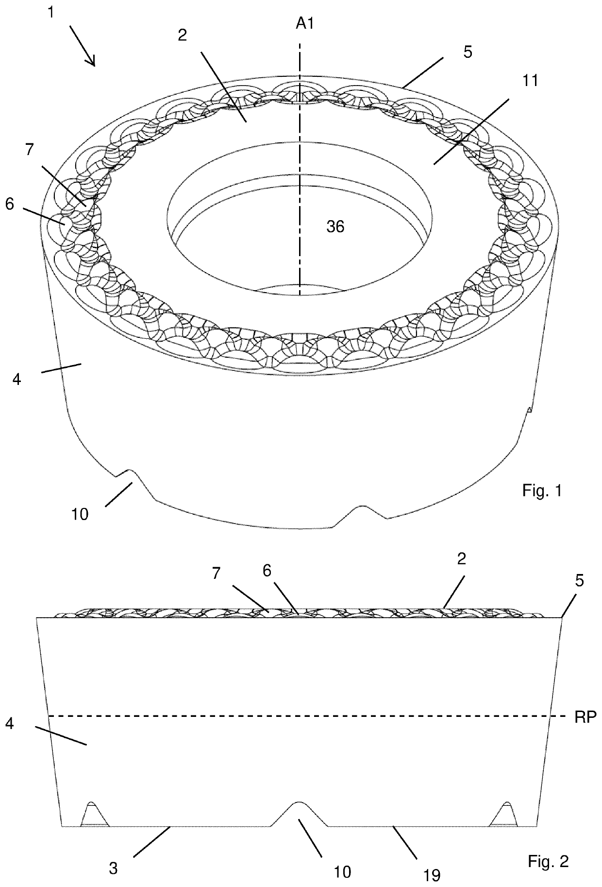
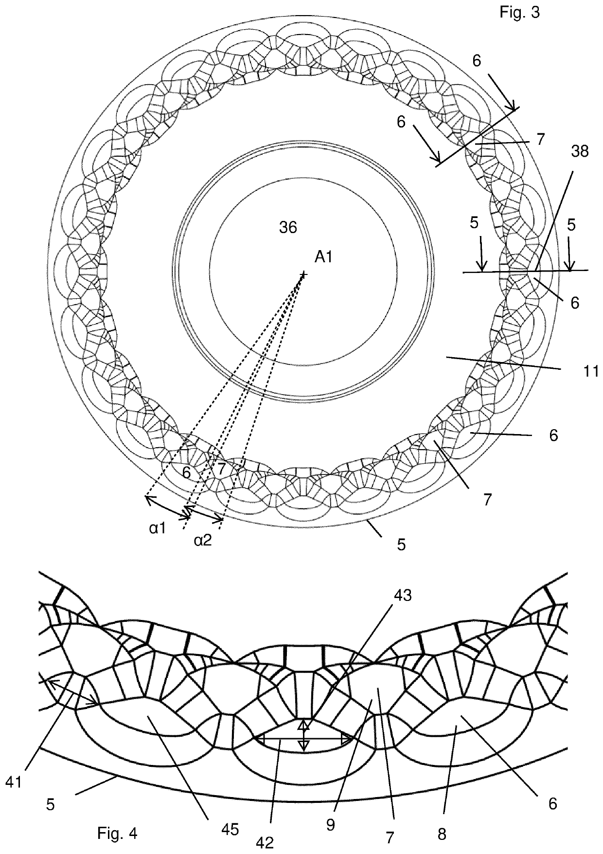
[0103]Reference is made to FIGS. 1-3, 7 and 8 which show a turning insert 1. The turning insert 1 comprises a top surface 2 comprising a rake surface and an opposite bottom surface 3 functioning as a seating surface. A reference plane RP extends mid-way between the top and bottom surfaces 2, 3. A center axis A1 intersects the top and bottom surfaces 2, 3. A side surface 4 connects the top surface 2 and the bottom surface 3. A cutting edge 5 is adjacent to the top surface 2 and the side surface 4. The cutting edge 5 is circular and concentric in relation to a center axis A1. A through hole 36 for a screw extends between the top and bottom surfaces 2, 3. The top surface 2 comprises a set of first protrusions 6.

[0104]As can be seen in FIGS. 5 and 6, a greatest distance from the reference plane RP to the first protrusions 6 is greater than a distance from the reference plane RP to the cutting edge 5.

[0105]As can best be seen in e.g. FIG. 8, the bottom surface 3 comprises a set of radial...


PUM


Abstract

A turning insert includes a top surface, an opposite bottom surface, and a reference plane therebetween. A center axis intersects the top and bottom surfaces and a side surface connects the top and bottom surfaces. A circular cutting edge is adjacent the top surface and the side surface. The top surface includes a set of first protrusions, which are elongated in a direction parallel to the adjacent cutting edge.. A greatest distance from the reference plane to the first protrusions is greater than a distance from the reference plane to the cutting edge. The bottom surface has a set of radial grooves and includes a set of flat surfaces. The flat surfaces extend in a plane parallel to the reference plane, wherein in a top view each first protrusion is symmetrical in relation to a line extending between the center axis and a mid-point of the first protrusion.

Description

TECHNICAL FIELD OF THE INVENTION[0001]The present invention belongs to the technical field of metal cutting. More specifically the present invention belongs to the field of tools for turning comprising a round turning insert.BACKGROUND OF THE INVENTION AND PRIOR ART[0002]The present invention refers to a turning insert according to the preamble of claim 1. In other words, the present invention relates to a turning insert comprising a top surface, an opposite bottom surface, a reference plane between the top and bottom surfaces, a center axis intersecting the top and bottom surfaces, a side surface connecting the top surface and the bottom surface, a cutting edge adjacent to the top surface and the side surface, the cutting edge being circular and concentric in relation to the center axis, wherein the bottom surface comprises a set of radial grooves.[0003]In turning of a metal work piece, the metal work piece rotates around a center axis. A turning tool is used to remove material fro...

Claims


Application Information

Patent Timeline
Patent Type & Authority Applications(United States)
IPC IPC(8): B23B27/16
CPCB23B27/1614B23B2200/0461B23B2205/16B23B2200/321B23B2205/12B23B2200/165
Inventor LOF, RONNIEMARELL, FREDRIK
Owner SANDVIK COROMANT
Why Eureka
Try Eureka