Turning insert

a turning insert and insert technology, applied in the field of metal cutting, can solve the problems of long chips or other undesirable shapes, and achieve the effect of improving the tool life of the turning insert and improving the breakage ra

Active Publication Date: 2021-08-31
SANDVIK INTELLECTUAL PROPERTY AB
View PDF44 Cites 0 Cited by
  • Summary
  • Abstract
  • Description
  • Claims
  • Application Information

AI Technical Summary

Benefits of technology

[0009]An object of the present invention is to provide a turning insert having improved chip breaking at low cutting depth, more specifically at cutting depths lower or equal than the nose radius, when turning metals such as low carbon steels or hardened steels. A further object is to increase the tool life of the turning insert under the same conditions.

Problems solved by technology

A common problem in turning of metal is that chips are long or otherwise have a shape which is not desirable, especially when turning e.g. low carbon steels at low depth of cut, i.e. a depth of cut which is smaller than the active nose radius of the turning insert.

Method used


Image

  • Turning insert
  • Turning insert
  • Turning insert

Examples


first embodiment

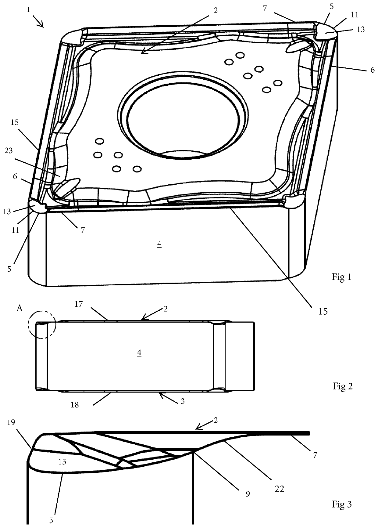
[0150]Reference is made to FIGS. 1-11, which show a turning insert 1 according to a The turning insert 1 has the dimension or general shape of the type commonly known as CNMG 120408. The turning insert 1 comprises a top surface 2, an opposite bottom surface 3, a circumferential side surface 4 connecting the top and bottom surfaces 2, 3 and a circumferential cutting edge 15 formed at an intersection of, or between, the top surface 2 and the side surface 4. The side surface 4 is a clearance surface. As seen in FIG. 8, a reference plane P2 extends equidistantly between the top and bottom surfaces 2, 3. The top surface 2 comprises a first flat surface 17 parallel to the reference plane P2, and the bottom surface 3 comprises a second flat surface 18 parallel to the reference plane P2. When a cutting edge 15 adjacent to the top surface 2 is active, the second flat surface 18 is a seating surface when the turning insert is mounted in a seat formed in a tool body not shown.

[0151]The top su...

third embodiment

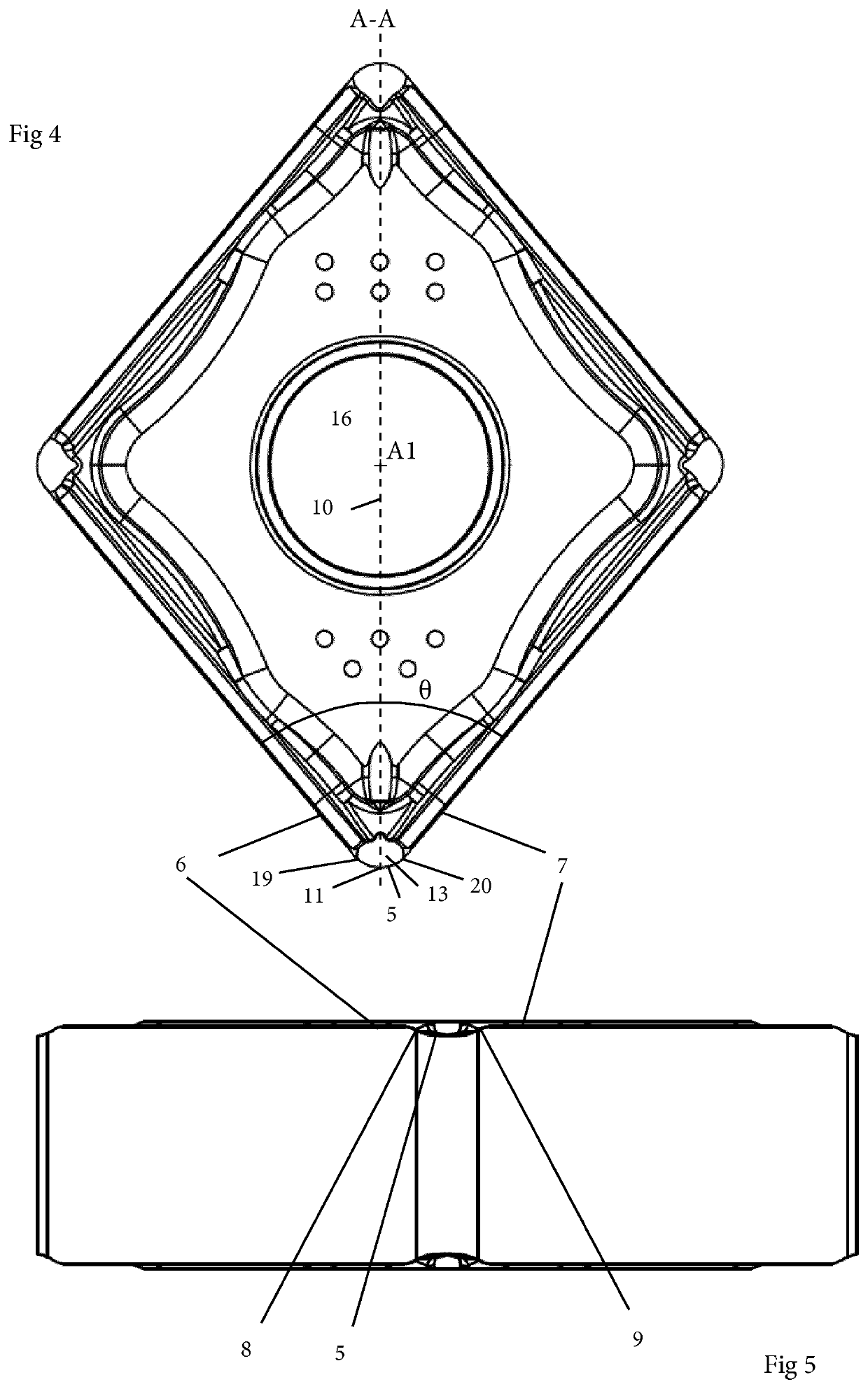
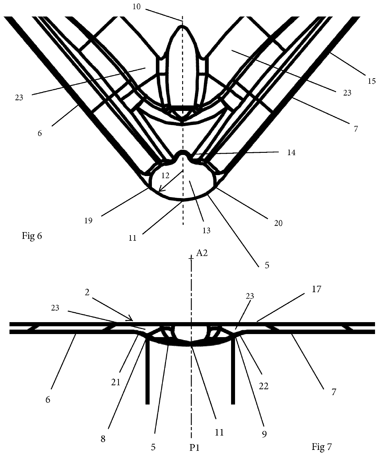
[0172]Reference is now made to FIGS. 17-20, which show a turning insert 1 which has a general shape and dimensions corresponding to what is commonly known as CNMG 120408. The turning insert 1 comprises a top surface 2, an opposite bottom surface 3 and a side surface 4 connecting the top and bottom surfaces 2, 3. The side surface 4 is a clearance surface. A cutting edge 15 is formed at an intersection of the top surface 2 and the side surface 4. The cutting edge 15 comprises a corner cutting edge 5, a first cutting edge 6 and a second cutting edge 7. The corner cutting edge 5 is convex in a top view, and the radius of curvature of the corner cutting edge 5 is 0.8 mm. A first end of the corner cutting edge 5 and the first cutting edge 6 are connected at a first transition point 8. An opposite second end of the corner cutting edge 5 and the second cutting edge 7 are connected at a second transition point 9. As seen in FIG. 17, a bisector 10 extending equidistantly between the first an...


PUM


Abstract

A turning insert includes a top surface, an opposite bottom surface, a side surface connecting the top and bottom surfaces, and a cutting edge formed at an intersection between the top surface and the side surface. The cutting edge including a corner cutting edge, a first cutting edge, and a second cutting edge. The top surface having a first surface in the form of a depression, which borders at least a major portion of the corner cutting edge. The first and the second cutting edges subtending an angle θ which is 75-85°. At least a part of the corner cutting edge is concave in a front view.

Description

RELATED APPLICATION DATA[0001]This application is a § 371 National Stage Application of PCT International Application No. PCT / EP2017 / 056901 filed Mar. 23, 2017 and EP 16175159.9 filed Jun. 20, 2016.TECHNICAL FIELD OF THE INVENTION[0002]The present invention belongs to the technical field of metal cutting. More specifically the present invention belongs to the field of turning inserts used for metal cutting in machines such as computer numerical control, i.e. CNC, machines.BACKGROUND OF THE INVENTION AND PRIOR ART[0003]The present invention relates to a turning insert comprising a top surface, an opposite bottom surface, a side surface connecting the top and bottom surfaces, a cutting edge formed at an intersection of the top surface and the side surface, the cutting edge comprising a corner cutting edge, a first cutting edge and a second cutting edge, wherein the corner cutting edge is convex in a top view, wherein a first end of the corner cutting edge and the first cutting edge ar...

Claims


Application Information

Patent Timeline
Patent Type & Authority Patents(United States)
IPC IPC(8): B23B27/14B23B27/16B23B27/22
CPCB23B27/141B23B27/143B23B27/1622B23B2200/086B23B2200/201B23B2200/3681B23B2260/104
Inventor PECINA, MICHAL
Owner SANDVIK INTELLECTUAL PROPERTY AB
Why Eureka
Try Eureka