Turning insert
a turning insert and insert technology, applied in the field of metal cutting, can solve the problems of long chips or other undesirable shapes, and achieve the effect of improving the tool life of the turning insert and improving the breakage ra
- Summary
- Abstract
- Description
- Claims
- Application Information
AI Technical Summary
Benefits of technology
Problems solved by technology
Method used
Image
Examples
first embodiment
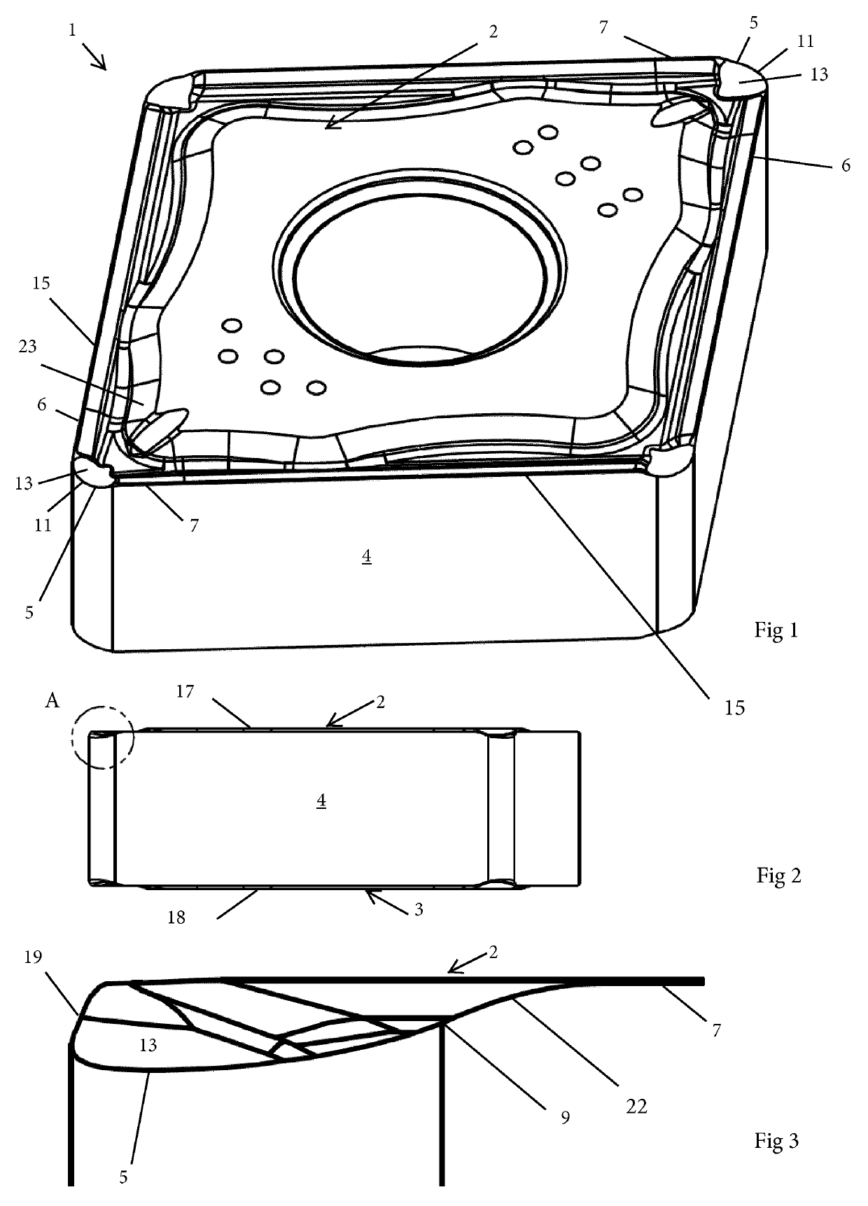
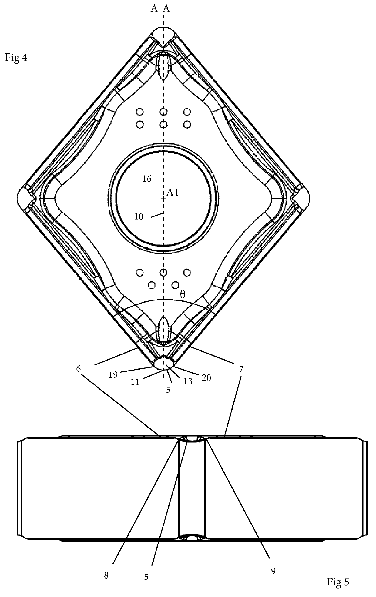
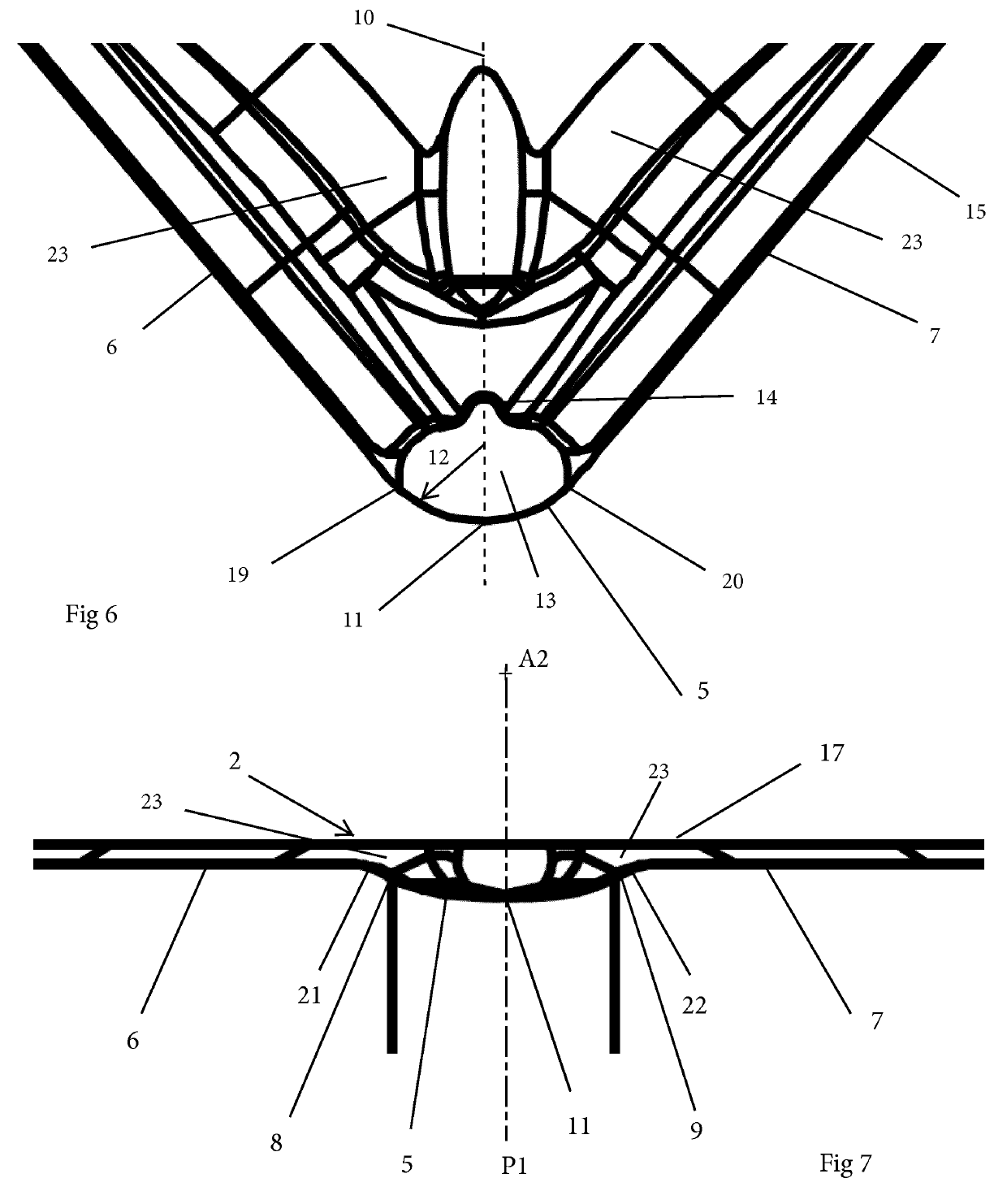
[0149]Reference is made to FIGS. 1-11, which show a turning insert 1 according to a The turning insert 1 has the dimension or general shape of the type commonly known as CNMG 120408. The turning insert 1 comprises a top surface 2, an opposite bottom surface 3, a circumferential side surface 4 connecting the top and bottom surfaces 2, 3 and a circumferential cutting edge 15 formed at an intersection of, or between, the top surface 2 and the side surface 4. The side surface 4 is a clearance surface. As seen in FIG. 8, a reference plane P2 extends equidistantly between the top and bottom surfaces 2, 3. The top surface 2 comprises a first flat surface 17 parallel to the reference plane P2, and the bottom surface 3 comprises a second flat surface 18 parallel to the reference plane P2. When a cutting edge 15 adjacent to the top surface 2 is active, the second flat surface 18 is a seating surface when the turning insert is mounted in a seat formed in a tool body not shown.
[0150]The top su...
third embodiment
[0171]Reference is now made to FIGS. 17-20, which show a turning insert 1 which has a general shape and dimensions corresponding to what is commonly known as CNMG 120408. The turning insert 1 comprises a top surface 2, an opposite bottom surface 3 and a side surface 4 connecting the top and bottom surfaces 2, 3. The side surface 4 is a clearance surface. A cutting edge 15 is formed at an intersection of the top surface 2 and the side surface 4. The cutting edge 15 comprises a corner cutting edge 5, a first cutting edge 6 and a second cutting edge 7. The corner cutting edge 5 is convex in a top view, and the radius of curvature of the corner cutting edge 5 is 0.8 mm. A first end of the corner cutting edge 5 and the first cutting edge 6 are connected at a first transition point 8. An opposite second end of the corner cutting edge 5 and the second cutting edge 7 are connected at a second transition point 9. As seen in FIG. 17, a bisector 10 extending equidistantly between the first an...
PUM
 Abstract
Description
Claims
Application Information
 - R&D
- Intellectual Property
- Life Sciences
- Materials
- Tech Scout
- Unparalleled Data Quality
- Higher Quality Content
- 60% Fewer Hallucinations
Browse by: Latest US Patents, China's latest patents, Technical Efficacy Thesaurus, Application Domain, Technology Topic, Popular Technical Reports.
© 2025 PatSnap. All rights reserved.Legal|Privacy policy|Modern Slavery Act Transparency Statement|Sitemap|About US| Contact US: help@patsnap.com


