Turning insert for metal cutting

a technology of turning inserts and metal cutting, which is applied in the direction of cutting inserts, turning machine accessories, metal-working apparatuses, etc., can solve the problems of poor chip control, disadvantages of using common turning inserts such as tnmg or tcm

Pending Publication Date: 2022-11-03
SANDVIK COROMANT
View PDF0 Cites 0 Cited by
  • Summary
  • Abstract
  • Description
  • Claims
  • Application Information

AI Technical Summary

Problems solved by technology

Although radial turning away from the rotational axis of the metal work piece, also known as out-facing, may be advantageous ...

Method used


Image

  • Turning insert for metal cutting
  • Turning insert for metal cutting
  • Turning insert for metal cutting

Examples


Embodiment Construction

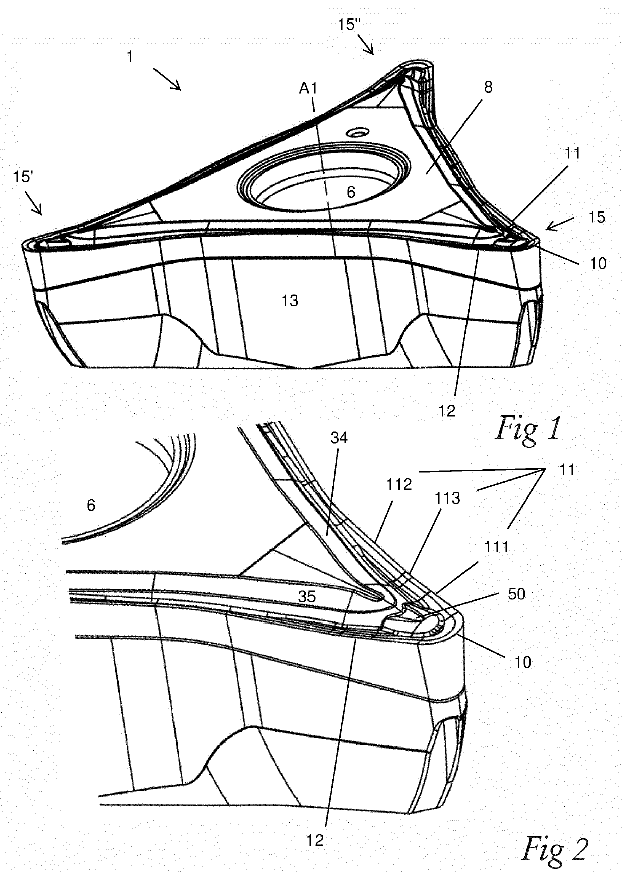
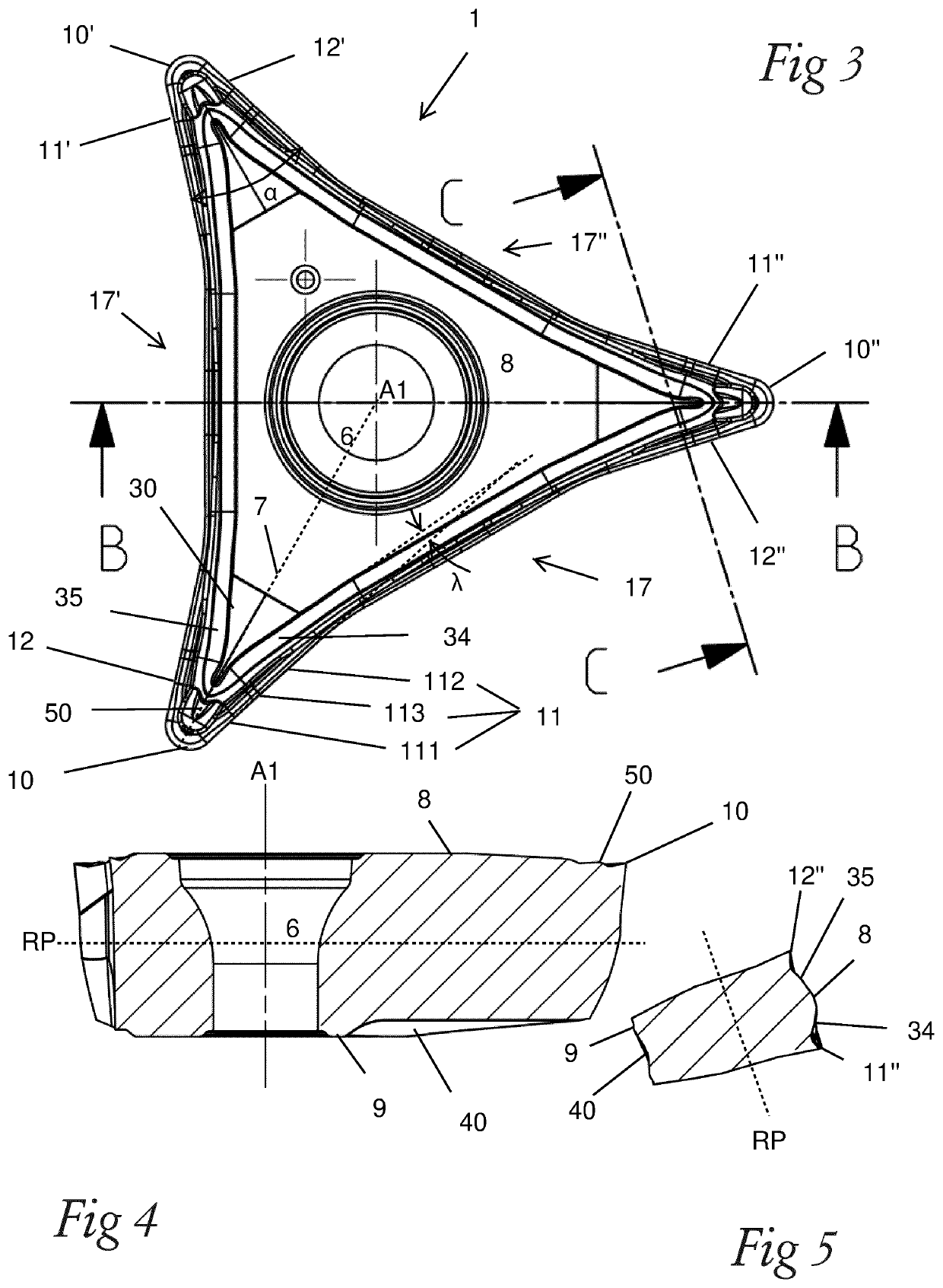
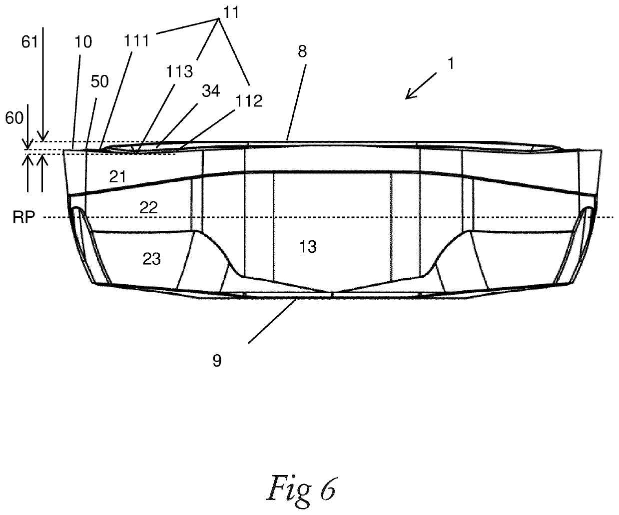
[0069]Reference is made to FIGS. 1-3, 6, 9a and 9b describes a turning insert 1 according to a first embodiment. The turning insert 1 comprises a top surface 8, which comprises a rake face, and an opposite bottom surface 9, functioning as a seating surface. A reference plane RP is located parallel to and between the top surface 8 and the bottom surface 9. A center axis A1 extends perpendicular to the reference plane RP and intersects the reference plane RP, the top surface 8 and the bottom surface 9. A hole, for a screw, having openings in the top surface 8 and the bottom surface 9 is concentric with the center axis A1. The turning insert 1 comprises side surfaces 13, functioning as clearance surfaces, connecting the top surface 8 and the bottom surface 9.

[0070]Three nose portions 15, 15′, 15″ are formed symmetrically relative to or around the center axis A1. The nose portions 15, 15′, 15″ are identical. Each nose portion 15, 15′, 15″ comprises a first cutting edge 11, a second cutt...


PUM


Abstract

A turning insert includes a top surface, a bottom surface, and side surfaces connecting the top and bottom surfaces. A reference plane is located parallel to and between the top surface and the bottom surface. A center axis intersects and extends perpendicular to the reference plane. Three nose portions are formed symmetrically around the center axis. Each nose portion has a first cutting edge, a second cutting edge and a convex nose cutting edge connecting the first and second cutting edges. As seen in in a top view, the first and second cutting edges on the same nose portion form a nose angle of 25-50°. The first cutting edge includes a first sub-portion and a second sub-portion. A distance from the nose cutting edge to the first sub-portion is shorter than a distance from the nose cutting edge to the second sub-portion.

Description

TECHNICAL FIELD OF THE INVENTION[0001]The present invention belongs to the technical field of metal cutting. More specifically the present invention belongs to the field of turning inserts used for metal cutting in machine tools such as CNC-machines.BACKGROUND OF THE INVENTION AND PRIOR ART[0002]The present invention refers to a turning insert according to the preamble of claim 1, a turning tool comprising such turning insert, and a method to machine a metal work piece using such turning tool. In other words, the present invention relates to a turning insert comprising a top surface, an opposite bottom surface, side surfaces connecting the top surface and the bottom surface, a reference plane located parallel to and between the top surface and the bottom surface, a center axis extending perpendicular to the reference plane and intersecting the reference plane, three nose portions formed symmetrically around the center axis, each nose portion comprising a first cutting edge, a second...

Claims


Application Information

Patent Timeline
IPC IPC(8): B23B27/14
CPCB23B27/145B23B2200/081B23B2200/201B23B2200/321
Inventor JOHANSSON, ADAMLOF, RONNIETRUONG, JOE
Owner SANDVIK COROMANT
Why Eureka
Try Eureka