Shift control method and shift control system

a technology of shift control and control method, which is applied in the direction of gearing control, mechanical equipment, transportation and packaging, etc., can solve the problems of shifting shock at the moment of clutch shift, vehicle may experience a slow down,

Pending Publication Date: 2022-08-04
NISSAN MOTOR CO LTD
View PDF0 Cites 2 Cited by
  • Summary
  • Abstract
  • Description
  • Claims
  • Application Information

AI Technical Summary

Benefits of technology

[0004]Considering such situations, an objective of this invention is to provide a shift control method and a shift control system that can suppress the occurrence of a shift shock at the accelerator stepping-in downshift.

Problems solved by technology

However, depending on the running conditions during which a shift is taking place, the vehicle may experience a slow down even under the driving force due to accelerator pedal operation.
In such a case, increasing correction of the target input shaft rotating speed may allow the input shaft rotating speed to exceed the final target value, resulting in a shift shock at the moment when the clutch engages.

Method used


Image

  • Shift control method and shift control system
  • Shift control method and shift control system
  • Shift control method and shift control system

Examples


Embodiment Construction

[0013]Hereinafter, embodiments of this invention are described referring to figures.

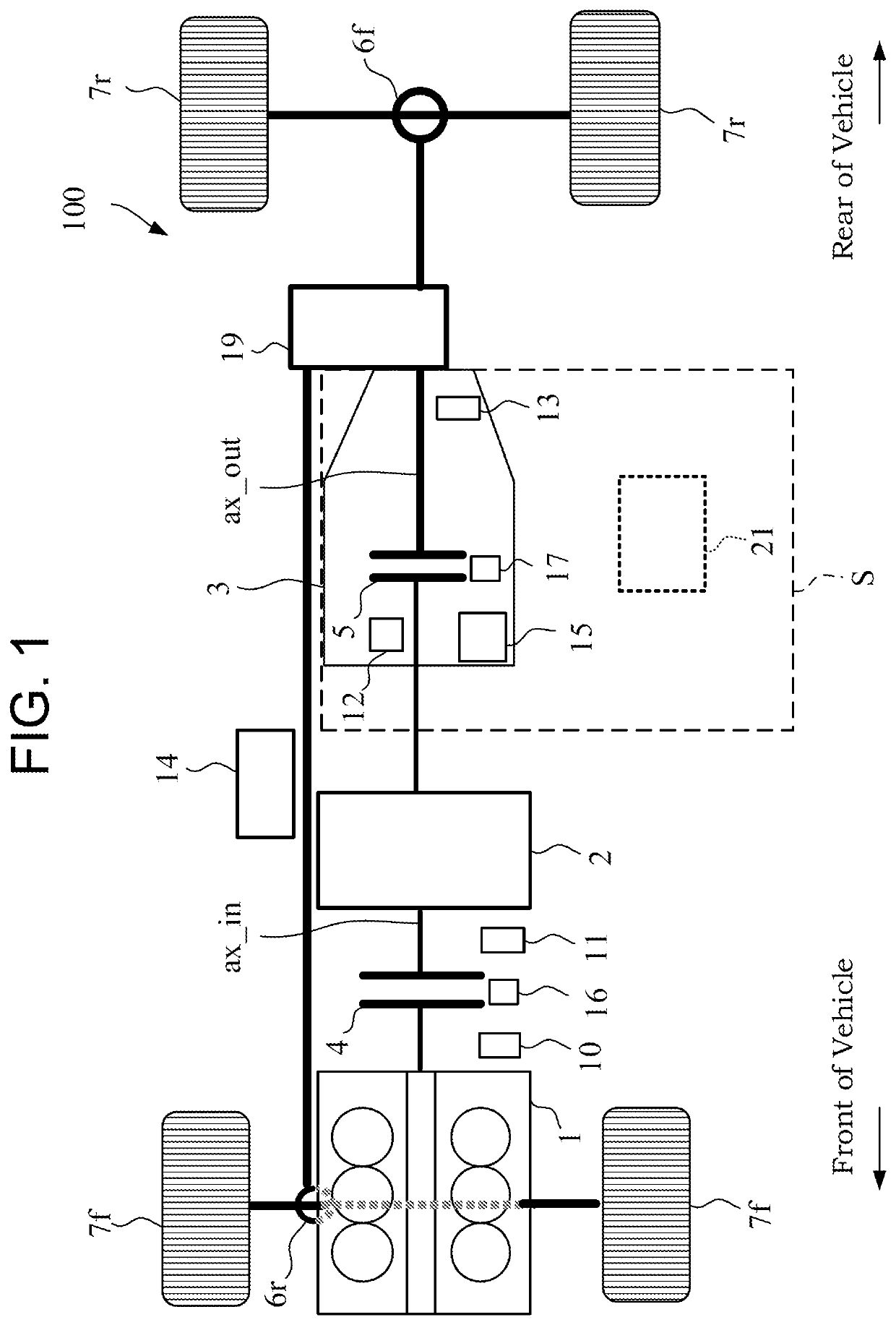
[0014]FIG. 1 shows a power train configuration of a vehicle 100, to which a shift control method of the embodiment is applied.

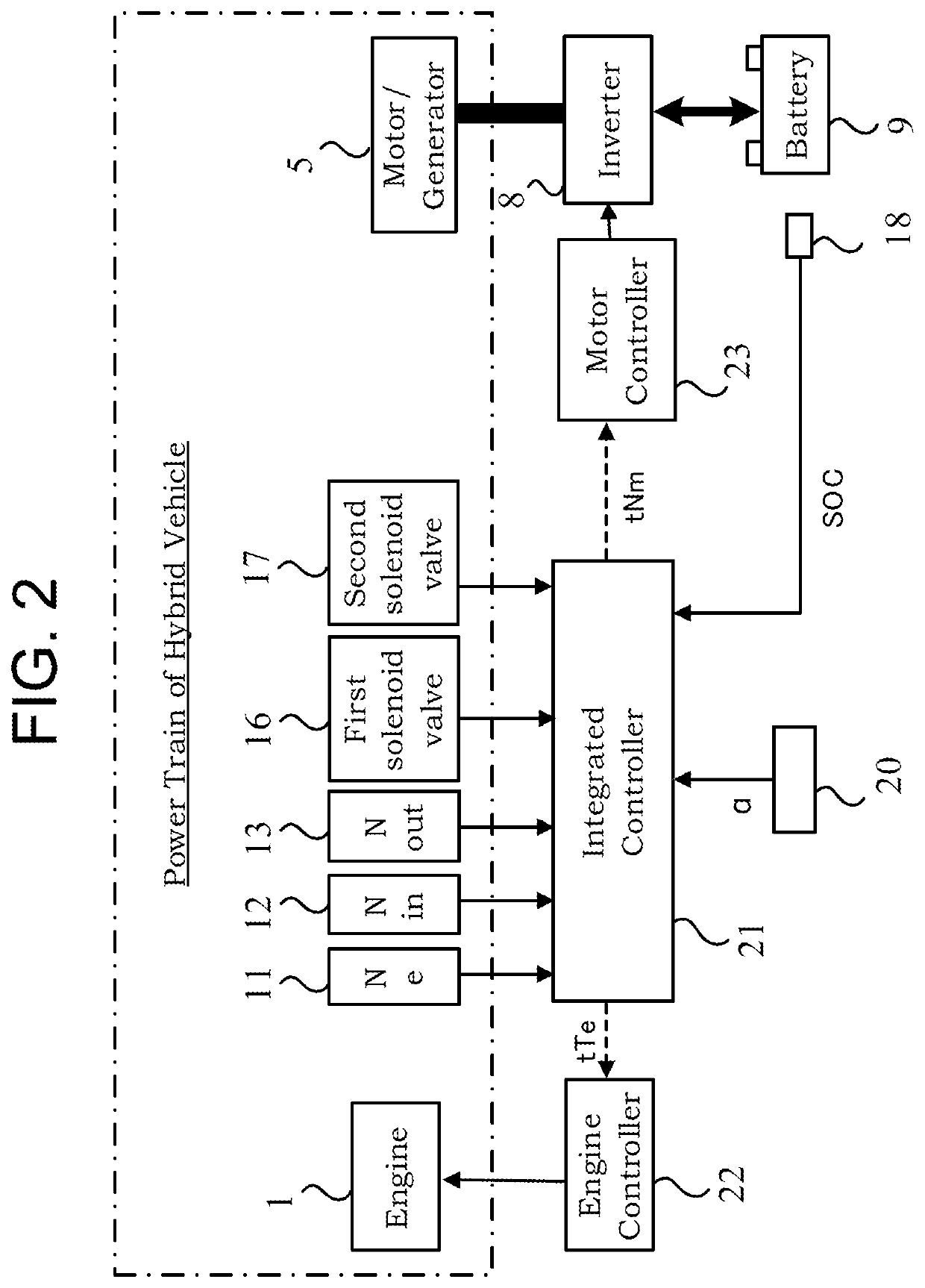
[0015]As shown in the figure, the vehicle 100 of the embodiment contains an internal combustion engine 1, a motor generator 2, an automatic transmission 3, and a transfer unit 19. In the embodiment, a shift control system S is configured by the automatic transmission 3 and an integrated controller 21 (to be further described later) acting as a shift controller.

[0016]Inside the vehicle 100 of the embodiment, the internal combustion engine 1, the motor generator 2 and the automatic transmission 3 are arranged in order from a front side toward running direction (or vehicle front) to a rear side. The internal combustion engine 1, the motor generator 2 and the automatic transmission 3 are mutually connected by way of an input shaft ax_in. In other words, the vehicle 100 of the embo...


PUM


Abstract

The present invention provides a shift control method include: setting a basic target synchronization rotation speed that is a basic target value of the input shaft rotation speed during the shift; determining whether or not an accelerating intention is present when the shift is a downshift with a driving force requirement to the vehicle; when the accelerating intention is present, setting a first target input shaft rotation speed as the target input shaft rotation speed, the first target input shaft rotation speed being obtained by increasingly correcting the basic target synchronization rotation speed; and when the accelerating intention is not present, setting a second target input shaft rotation speed as the target input shaft rotation speed, the second target input shaft rotation speed being obtained by maintaining or decreasingly correcting the basic target synchronization rotation speed.

Description

TECHNICAL FIELD[0001]The present invention relates to a shift control method and a shift control system.BACKGROUND ART[0002]In a conventional shift control system as disclosed in JP2008-32185A, a decision is first made whether or not a downshift accompanied by a stepping-in of the accelerator pedal. Hereinafter, the downshift is also described as “accelerator stepping-in downshift”. If the shift operation is judged to be the accelerator stepping-in downshift, a target input shaft rotating speed is set by increasingly correcting a basic target synchronizing speed, whereby acceleration of the vehicle during the shift is assumed. The basic target synchronizing speed is a basic target value of the input shaft rotation speed during the shift.SUMMARY OF INVENTION[0003]However, depending on the running conditions during which a shift is taking place, the vehicle may experience a slow down even under the driving force due to accelerator pedal operation. In such a case, increasing correction...

Claims


Application Information

Patent Timeline
Patent Type & Authority Applications(United States)
IPC IPC(8): F16H61/04F16H59/18F16H59/42F16H59/66B60W20/30F16H63/50
CPCF16H61/04F16H59/18F16H59/42F16H2061/0474B60W20/30F16H63/502F16H59/66F16H2061/0492B60Y2200/92F16H2061/0422F16H61/0403F16H59/48
Inventor SHIMOYAMA, HIROKIUENO, MUNETOSHISUZUKI, TAKEFUMI
Owner NISSAN MOTOR CO LTD
Why Eureka
Try Eureka