Eureka AIR delivers breakthrough ideas for toughest innovation challenges, trusted by R&D personnel around the world.

Polarizing plate and liquid crystal display comprising the same

a technology of liquid crystal display and polarizing plate, which is applied in the direction of polarizing elements, instruments, optics, etc., can solve the problems of retardation film enlargement, color deviation, and gradual deterioration of contrast ratio and color deviation of liquid crystal display from a front side, and achieve the limitation of enlargement of viewing angle of scattering particle-containing film and/or improvement of external appearan

Pending Publication Date: 2022-08-04
SAMSUNG SDI CO LTD
View PDF5 Cites 0 Cited by
  • Summary
  • Abstract
  • Description
  • Claims
  • Application Information

AI Technical Summary

Benefits of technology

[0006]According to an aspect of embodiments of the present invention, a polarizing plate is capable of improving brightness, viewing angle, and contrast ratio at a front side and a lateral side in application to a liquid crystal display including a light-collecting backlight unit.
[0007]According to another aspect of embodiments of the present invention, a polarizing plate is capable of improving front contrast ratio, lateral contrast ratio, and external appearance in application to a liquid crystal display including a light-collecting backlight unit.
[0008]According to another aspect of embodiments of the present invention, a polarizing plate is capable of reducing deviation in ratio of brightness at a lateral side to brightness at a front side depending upon an angle of the lateral side in application to a liquid crystal display including a light-collecting backlight unit.
[0009]According to another aspect of embodiments of the present invention, a liquid crystal display includes a light-collecting backlight unit, has improved brightness, viewing angle, and contrast ratio at a front side and a lateral side, and has reduced deviation in ratio of brightness at a lateral side to brightness at a front side depending upon an angle of the lateral side.

Problems solved by technology

As a result, the liquid crystal display suffers from gradual deterioration in contrast ratio and color deviation from a front side to a lateral side while light passes through the light source-side polarizing plate, the liquid crystal panel, and the viewer-side polarizing plate.
However, it is difficult for the retardation film to achieve complete compensation of light from the front side to the lateral side and to prevent light leakage, particularly in a diagonal direction.
Although a scattering particle-containing film may be used as the optical device to be disposed on the outermost surface of the viewer-side polarizing plate, there is a limitation in terms of enlargement of viewing angle of the scattering particle-containing film and / or improvement in external appearance thereof.

Method used


Image

  • Polarizing plate and liquid crystal display comprising the same
  • Polarizing plate and liquid crystal display comprising the same
  • Polarizing plate and liquid crystal display comprising the same

Examples


example 1

[0153]A first resin layer (high-refractivity layer) was formed of a composition comprising a UV-curable resin (SHIN-A T&C Co., Ltd.) having a refractive index of 1.62. A second resin layer (low-refractivity layer) was formed of a composition comprising a UV-curable resin (SHIN-A T&C Co., Ltd.) having a refractive index of 1.47.

[0154]A coating layer was formed by depositing a composition for a second resin layer to a predetermined thickness on one surface (light incident surface) of a polyethylene terephthalate (PET) film (TA044, thickness: 80 μm, Toyobo Co., Ltd.) as a protective film. The second resin layer was formed on the coating layer by applying an optical pattern thereto using a film having an optical pattern formed thereon, followed by UV curing at 500 mJ / cm2. Then, a first resin layer was formed on one surface of the second resin layer by coating a composition for the first resin layer, followed by UV curing at 500 mJ / cm2. Next, a polarizer having a PET / PVA / COP triple layer...

examples 2 and 3

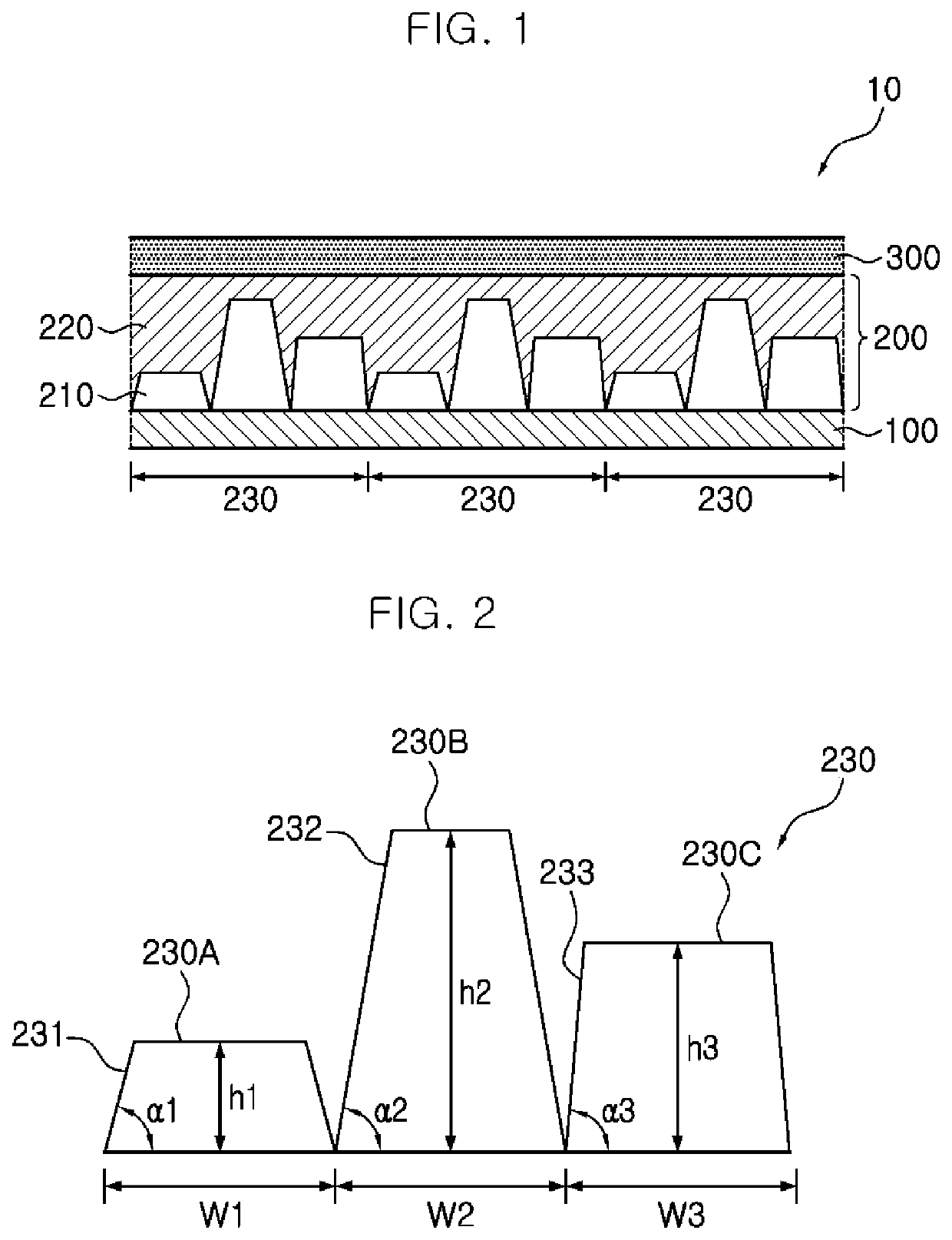
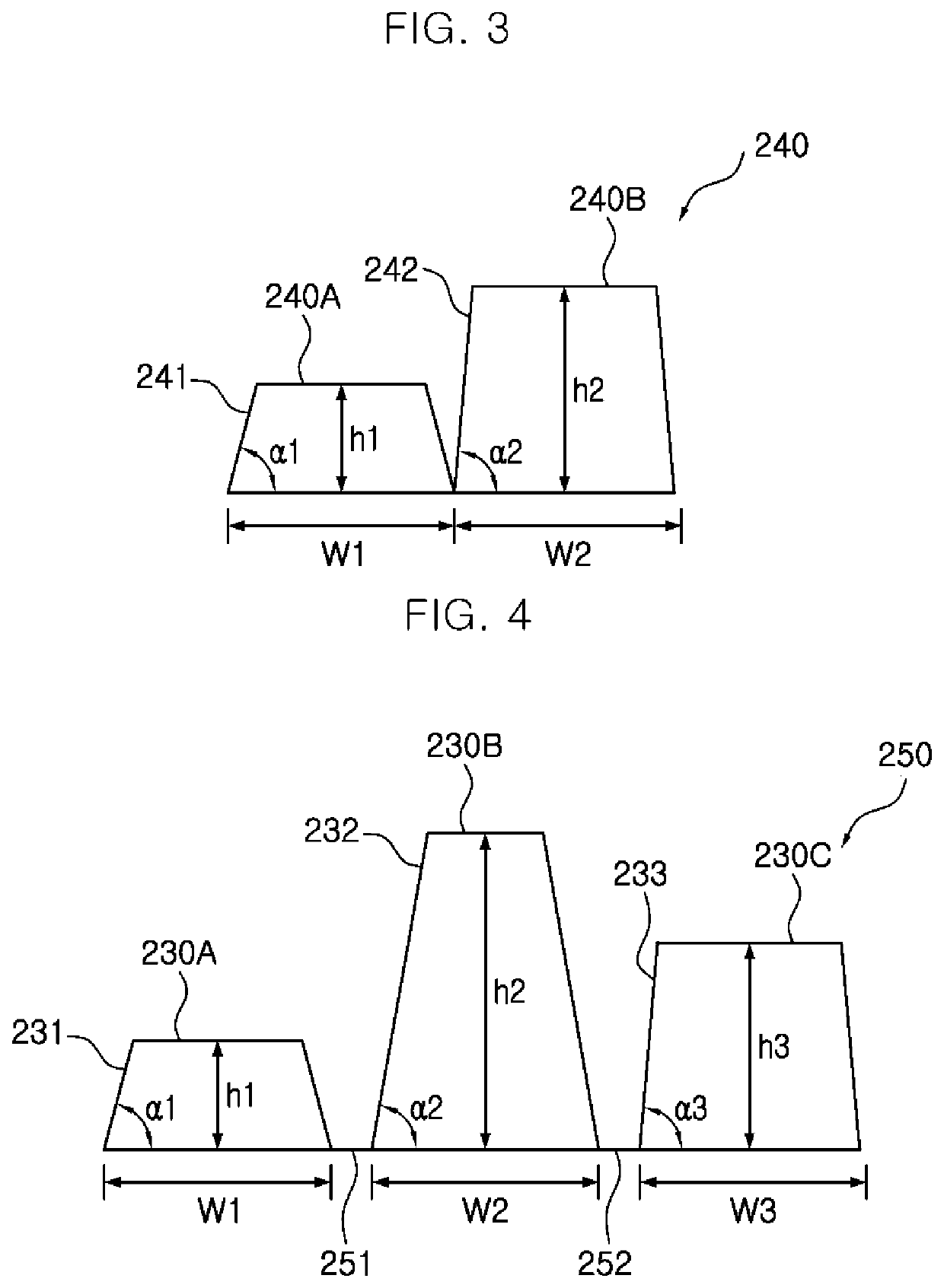
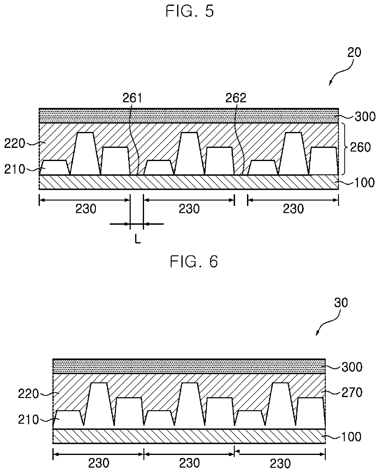
[0157]Polarizing plates were manufactured in the same manner as in Example 1 except that the pattern group was composed of three patterns, that is, a first pattern, a second pattern, and a third pattern sequentially arranged in the stated order without a flat section, and each of the first pattern, the second pattern, and the third pattern was an engraved trapezoidal pattern and had a base angle and an aspect ratio, as shown in Table 1.

example 4

[0158]A polarizing plate was manufactured in the same manner as in Example 1 except that the pattern group was composed of two patterns, that is, a first pattern and a second pattern, sequentially arranged in the stated order without a flat section, and each of the first pattern and the second pattern was an engraved trapezoidal pattern and had a base angle and an aspect ratio, as shown in Table 1.


PUM

PropertyMeasurementUnit
aspect ratioaaaaaaaaaa
base angleaaaaaaaaaa

Abstract

A polarizing plate and a liquid crystal display including the same are provided. A polarizing plate includes: a polarizer; and a pattern layer on a light exit surface of the polarizer, the pattern layer including a first resin layer and a second resin layer sequentially arranged on the polarizer, a pattern portion being located at an interface between the first resin layer and the second resin layer and being composed of at least two pattern groups repeatedly arranged therein, each of the pattern groups including at least two engraved optical patterns; and at least two of the engraved optical patterns in each of the pattern groups having different aspect ratios and different base angles.

Description

CROSS-REFERENCE TO RELATED APPLICATION[0001]This application is a continuation of U.S. application Ser. No. 16 / 556,107, filed on Aug. 29, 2019, which claims priority to and the benefit of Korean Patent Application No. 10-2018-0104006, filed on Aug. 31, 2018, and Korean Patent Application No. 10-2019-0096380, filed on Aug. 7, 2019, in the Korean Intellectual Property Office, the entire disclosures of all of which are incorporated herein by reference.1. FIELD[0002]Aspects of embodiments of the present invention relate to a polarizing plate and a liquid crystal display including the same.2. DESCRIPTION OF THE RELATED ART[0003]A liquid crystal display is operated to allow light emitted from a backlight unit to sequentially pass through a light source-side polarizing plate, a liquid crystal panel, and a viewer-side polarizing plate. Light emitted from a light source spreads while passing through the backlight unit and then enters the light source-side polarizing plate. As a result, the l...

Claims


Application Information

Patent Timeline
Patent Type & Authority Applications(United States)
IPC IPC(8): G02B5/30G02F1/1335
CPCG02B5/3025G02F1/133528G02B5/305
Inventor WEE, DONG HOLEE, JEONG HOOH, YOUNG
Owner SAMSUNG SDI CO LTD
Why Eureka
Eureka Blog
Learn More