Spring contact ring

a contact ring and spring technology, applied in the direction of coupling contact members, coupling device connections, therapy, etc., can solve the problems of complicated manufacturing, more susceptible to design errors,

Pending Publication Date: 2022-08-11
HERAEUS PRECIOUS METALS GMBH & CO KG
View PDF0 Cites 0 Cited by
  • Summary
  • Abstract
  • Description
  • Claims
  • Application Information

AI Technical Summary

Problems solved by technology

Contact elements used in the prior art usually consist of several components and are therefore mor

Method used


Image

  • Spring contact ring
  • Spring contact ring
  • Spring contact ring

Examples


examples

[0064]The invention is further illustrated below using examples, which, however, are to be understood as not limiting. It will be apparent to the person skilled in the art that other equivalent means may be similarly used in place of the features described here.

Figures

[0065]The figures show by way of example various embodiments of the spring contact rings described herein.

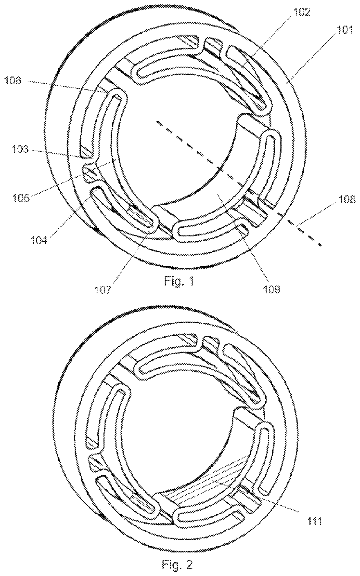
[0066]FIG. 1 shows a perspective view of a spring contact ring according to the invention.

[0067]The spring contact ring comprises an outer ring 101, which comprises a plurality of spring elements 102. The outer ring 101 has an imaginary central axis 108. Each spring element 102 comprises a first connector 103 and a second connector 104 via which it in each case is directly connected to the outer ring 101. The connectors 103, 104 have a curved shape. The angle of this curvature can be approximately 90° or slightly less, for example between 75° and 90°.

[0068]In this example, the outer ring 101 and the spring elements...


PUM


Abstract

The present invention relates to a monolithic spring contact ring, preferably for use in a medical electrode, comprising an outer ring and a plurality of elastically deformable belt-shaped spring elements, each comprising two curved connectors which form a continuously running, gap-free connection between the outer ring and the respective spring element, wherein the spring elements each extend continuously from the first connector to the second connector via a first bend, a central part of the spring element and a second bend, wherein the middle part comprises a front side which points in the direction of the central axis of the outer ring.

Description

CROSS-REFERENCE TO RELATED APPLICATIONS[0001]This application claims priority pursuant to 35 U.S.C. 119(a) to German Patent Application No. 102021102864.7, filed February 8, 2021, which application is incorporated herein by reference in its entirety.FIELD OF THE INVENTION[0002]The invention relates to a spring contact ring, which can be used in particular in the field of medical technology, for example in pulse generators which are used in connection with active implantable medical devices.TECHNICAL BACKGROUND[0003]Spring contact elements serve to connect two different electrical components. In the field of medical technology, special demands are made on the reliability of these components. For example, such a contact element should ensure a stable electrical connection even after the contact pin has been inserted and removed multiple times. An exemplary spring contact element for use in the field of medical technology is disclosed in EP2614856A1. Contact elements used in the prior ...

Claims


Application Information

Patent Timeline
IPC IPC(8): H01R13/11H01R13/03A61N1/375
CPCH01R13/111H01R2201/12A61N1/3752H01R13/03
Inventor JUNG, MARKUSROTH, JOSEF
Owner HERAEUS PRECIOUS METALS GMBH & CO KG
Why Eureka
Try Eureka