Mixing and discharge system for bone replacement material

a discharge system and bone replacement technology, applied in the field of mixing and discharge system, can solve the problems of time-consuming operation and the risk of material falling from the spatula in the course of its discharg

Inactive Publication Date: 2019-07-25
SULZER MIXPAC AG
View PDF0 Cites 1 Cited by
  • Summary
  • Abstract
  • Description
  • Claims
  • Application Information

AI Technical Summary

Benefits of technology

[0009]An object of the present invention is to provide a mixing and discharge system for impregnating granulate with a liquid and for discharging the mixture, which ensures the effective impregnation of the granulate and discharge of the mixture and offers simple operation in the process. The mixing and discharge system should also lend itself to simple and cost-effective manufacture.

Problems solved by technology

This may prove to be difficult, or even impossible, depending on the location of the intended destination, and, since the material lies in a loose pile on the spatula, there is a risk of the material falling from the spatula in the course of its discharge.
An operation of this kind is time-consuming in addition, and care must be taken during preparation to ensure that the granulate and the liquid phase are mixed together in the correct proportion, so that the bone graft material has the desired paste-like consistency.

Method used


Image

  • Mixing and discharge system for bone replacement material
  • Mixing and discharge system for bone replacement material
  • Mixing and discharge system for bone replacement material

Examples


first embodiment

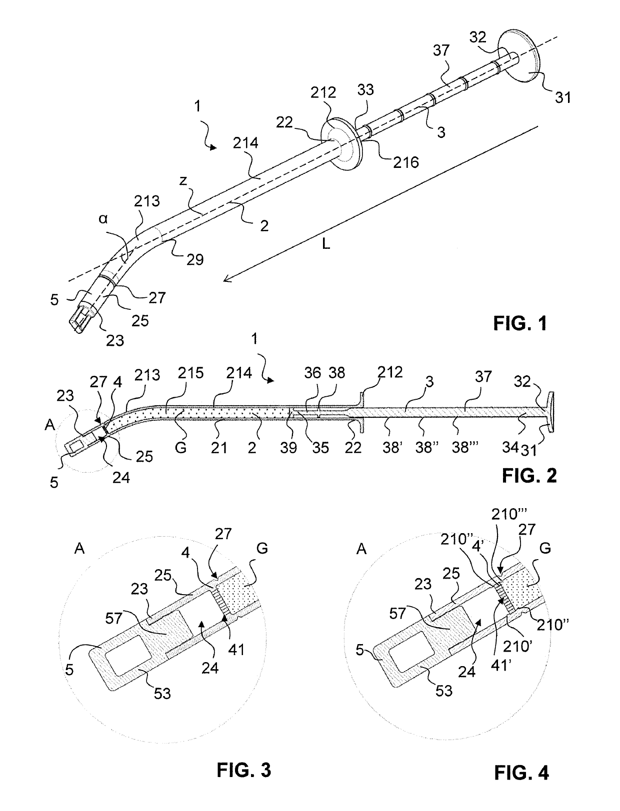
[0061]In FIGS. 1 to 3, an inventive mixing and discharge apparatus 1 is illustrated in various views. The mixing and discharge apparatus 1 comprises a container 2 having a separation element 4 as well as a feed element 3 displaceably mounted in the container 2 for discharging a mixture in a distal discharge direction L. The container 2 is closed by a closure 5.

[0062]The distal discharge direction L is defined as the direction along which the feed element 3 moves into the container 2, in order to discharge the mixture from the container 2. The direction opposite thereto is referred to as the proximal direction.

[0063]The container 2 has a circumferential container wall 21, which delimits a cylindrical interior space 215 of the container for receiving a granulate G, as well as a proximal container end 22 and a distal container end 23.

[0064]The proximal container end 22 forms an inlet opening 216, which opens into the interior space 215 of the container. Once the granulate G has been fi...

second embodiment

[0071]Represented in FIG. 4 is a separation element 4′ which, unlike the integrally formed separation element in FIGS. 1 to 3, is formed separately from the container 2 and can be introduced subsequently into the interior space 215 of the container.

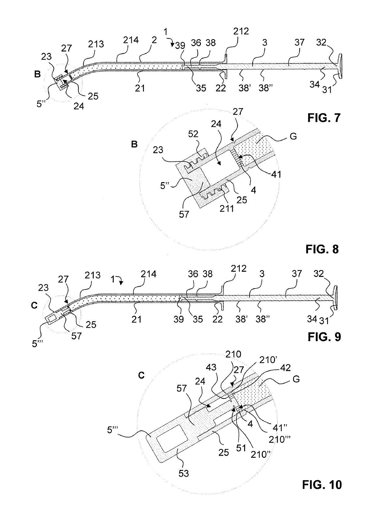
[0072]As can be appreciated from FIGS. 1 to 4, the closure 5 has a plug 57 and is pushed together with it into the container opening 24. In the distal direction, the closure 5 protrudes beyond the distal container end 23 and is provided with a grip 53, which can be grasped firmly by a user for the purpose of removing the closure 5.

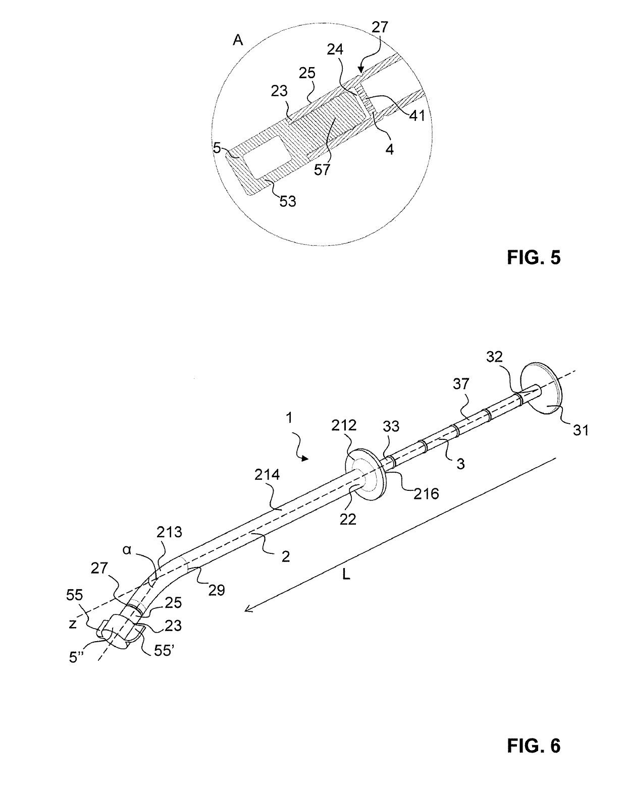
[0073]Whereas the closure 5 in this case projects only partially into the container opening 24 and is arranged in the container 2 at a distance from the separation element 4, however, the closure can also have a plug which extends through the distal end region 25 as far as the separation element 4. A suchlike closure 5′ is depicted in FIG. 5 and has the additional advantage that it prevents fine granules, of wh...


PUM


Abstract

A mixing and delivery system (1) and a method for impregnating granules (G) with a liquid and for delivering a resulting mixture are specified. The mixing and delivery system (1) has a container (2) for holding the granules. In a distal end region (25) of the container is arranged a separation element (4), which is designed to retain granules but allow liquid to pass through. The container has a predefined breaking point (27) proximal of the separation element (4) so that the distal end region between the predefined breaking point and the distal container end (23) can be broken off from the container together with the separation element (4), thereby creating a delivery opening on the container for delivering the mixture.

Description

TECHNICAL FIELD[0001]The present invention relates to a mixing and discharge system and a corresponding method for impregnating granulate with a liquid and for discharging the mixture.PRIOR ART[0002]Bone graft materials find an application in various fields of medicine, such as dentistry, orthopedics or reconstructive surgery. The bone graft material consists mostly of a granular (particulate) phase of natural or synthetic origin (for example a two-phase calcium phosphate / hydroxyl apatite material) and a liquid phase (for example endogenous blood or a physiological sodium chloride solution). The bone graft material usually has a paste-like consistency.[0003]The granular material, hereinafter referred to as granulate, is traditionally supplied in a bowl and the liquid phase is added, whereby the granulate is wetted. In order to apply the resultant finished bone graft material to the patient, it is brought to the intended destination with a spatula. This may prove to be difficult, or ...

Claims


Application Information

Patent Timeline
Patent Type & Authority Applications(United States)
IPC IPC(8): A61B17/88A61F2/46
CPCA61B17/8825A61F2/4644A61B17/8833A61B2017/8838
Inventor NIEBER, BENJAMIN
Owner SULZER MIXPAC AG
Why Eureka
Try Eureka