Refrigerator

a technology of refrigerators and air conditioners, applied in the field of refrigerators, can solve the problems of limited functionality when bypassing the seal and are significantly reduced, and achieve the effects of facilitating the use of optional heating elements, increasing local strength, and cost-effectiveness

Active Publication Date: 2022-05-03
BSH BOSCH & SIEMENS HAUSGERAETE GMBH
View PDF19 Cites 0 Cited by
  • Summary
  • Abstract
  • Description
  • Claims
  • Application Information

AI Technical Summary

Benefits of technology

[0014]According to one embodiment, it is provided that a seal stop is arranged in the passage section, said seal stop being in contact with a section of the seal in at least one operating state of the seal. Thus the seal stop is able to prevent and / or limit the seal being pushed into the passage section. In this manner, the seal may be prevented from blocking the at least two passage channels. The at least one operating state may, for example, be an operating state which occurs in the case of a refrigerator when the closure element is closed and an internal pressure prevails in the storage chamber which substantially corresponds to an external pressure in the surroundings of the refrigerator (normal operating state). Accordingly, in this regularly occurring operating state the seal stop already prevents the seal from being pushed into the passage section. The at least one operating state, however, may also be an operating state which is present in the case of a refrigerator when the closure element is closed and an internal pressure prevails in the storage chamber which is lower than an external pressure in the surroundings of the refrigerator (temperature compensating operating state). This operating state is produced after the opening of the closure element, the resulting forced inflow of relatively warm ambient air into the storage chamber and a subsequent closure of the closure element. In this variant, it may be provided that the seal stop is designed such that whilst the seal is in contact therewith in the temperature compensating operating state, in the normal operating state a gap is present between the seal and seal stop. In this variant, therefore, the seal is not in contact with the seal stop in the normal operating state. In the normal operating state, therefore, a relatively large flow cross-section is available for the inflow of air into the storage chamber, whilst at least a minimal flow cross-section is present in the temperature compensating operating state. According to this embodiment, the section of the seal in contact with the seal stop may, for example, be formed entirely or partly by a sealing foot. Two, three, four or more seal stops may be arranged in the passage section. It is conceivable that the two, three, four or more seal stops are configured identically or at least substantially identically to one another and / or are arranged adjacent to passage channels. In particular, it is conceivable that in each case a seal stop and a passage channel preferably alternate in the longitudinal direction of the seal receptacle.
[0015]According to one embodiment, it is provided that the at least two passage channels are arranged in an immediate vicinity. In this case, “immediate vicinity” is to be understood as a notional cube which is as small as possible enclosing the passage channels, having a maximum edge length of less than 30 cm, preferably of less than 20 cm, further preferably of less than 15 cm and even further preferably of less than 10 cm. Thus, for example, it may be provided that in the longitudinal direction of the seal receptacle the passage section extends over less than 30 cm, preferably over less than 20 cm, further preferably over less than 15 cm, even further preferably over less than 10 cm. It is also conceivable that a maximum spacing of the at least two passage channels is less than 20 cm, preferably less than 10 cm, further preferably less than 5 cm and even further preferably less than 3 cm. As a result, a very compact construction of the passage section is possible with a noticeable increase in the local strength. Moreover, the use of an optional heating element is facilitated: if an electrical heating element or a so-called hot gas line of the refrigerant circuit is intended to heat the passage section to a minimum temperature in order to avoid condensation of water in this section, the heating element may be designed to be correspondingly compact, simple and cost-effective. According to one embodiment, therefore, it is provided that a heating element is arranged in an immediate vicinity of the passage section, in particular the heating element is arranged solely in the immediate vicinity of the passage section.
[0016]According to one embodiment, it is provided that the at least two passage channels, in particular the passage section, are configured integrally in a component comprising the seal receptacle. The increase in strength of the passage section thus has an effect at the same time on the component comprising the seal receptacle. In particular, it may be provided that this component consists of plastic material. For example, it may be a plastic blank which is reshaped by thermoforming. This embodiment also permits simple and cost-effective manufacture since the seal receptacle and the passage channels, in particular the passage section, may be configured in one manufacturing step. In this embodiment, it is provided that the seal receptacle and the passage section are integrally configured in an inner wall of the closure element, for example the door, facing the storage chamber. The inner wall may in this case, in particular, correspond to a so-called inner liner. It is conceivable that the inner wall is partly or entirely produced by thermoforming. In order to permit production without the use of additional sliders in the thermoforming tool, it may be provided that the seal receptacle and / or the passage section including the at least two passage channels, when viewed perpendicular to a main extension plane of the inner wall, is configured to be at least substantially without undercuts.

Problems solved by technology

Undesired—or even merely small—deformations in this critical region, which may lead to a limited functionality when bypassing the seal, are significantly reduced.

Method used


Image

  • Refrigerator
  • Refrigerator
  • Refrigerator

Examples


Embodiment Construction

[0035]Elements which are the same or functionally the same are provided with the same reference characters.

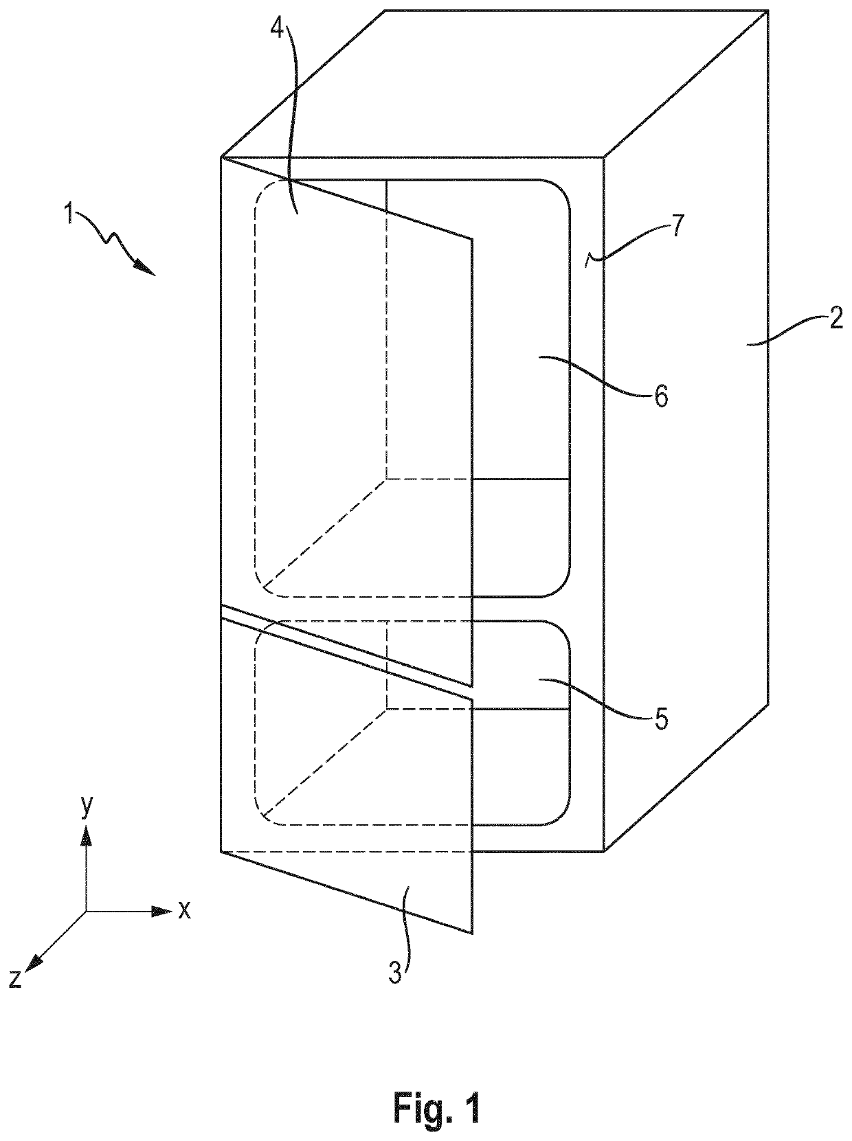
[0036]A simplified view of a household refrigerator 1 as an example of a refrigerator according to the invention which is a combined fridge-freezer and which is configured to receive foodstuffs is shown in FIG. 1. The household refrigerator 1 comprises a body 2 and two doors 3, 4 as closure elements. The doors 3, 4 are fastened in an articulated manner to the body 2 and serve for closing two storage chambers 5, 6. A front face 7 which is configured in two parts on the body and faces the doors 3, 4 serves as a stop surface for seals, not shown, which are fastened to the lower door 3 and the upper door 4 in a seal receptacle.

[0037]Both doors 3, 4 comprise an outer door wall and an inner door wall which together delimit a hollow space filled with insulating material. The seals are arranged in seal receptacles on the respective inner door walls.

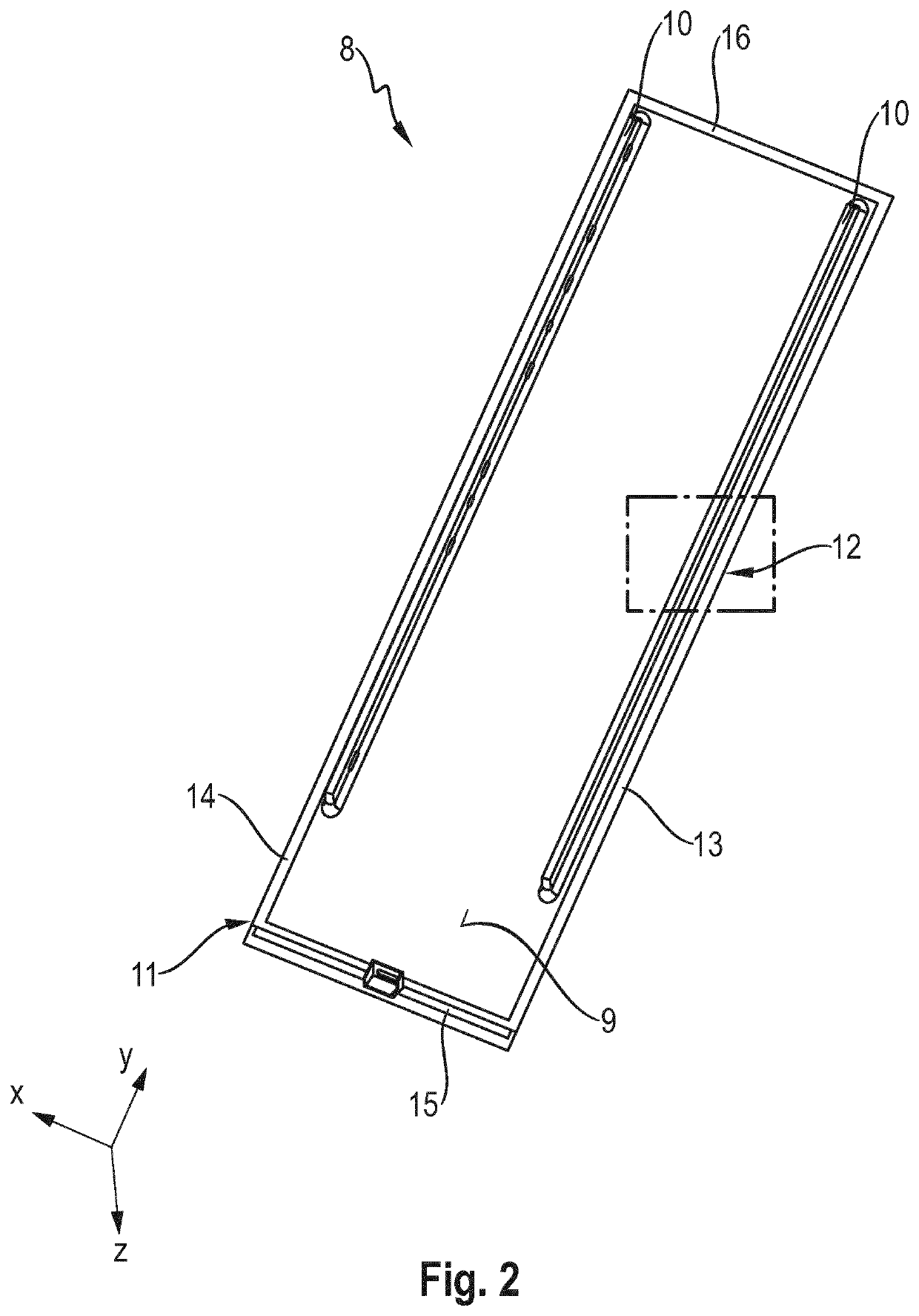
[0038]The inner wall 8 of the door 4 ...


PUM

PropertyMeasurementUnit
angleaaaaaaaaaa
angleaaaaaaaaaa
angleaaaaaaaaaa

Abstract

A refrigerator, in particular a domestic refrigerator, has a body and a closure element, which jointly delimit a storage chamber. A seal is provided, which is arranged between the body and the closure element and which is at least partly arranged in a seal receptacle. The seal receptacle has a passage section for bypassing the seal. Accordingly, the passage section has at least two passage channels.

Description

BACKGROUND OF THE INVENTIONField of the Invention[0001]The invention relates to a refrigerator, in particular a household refrigerator, comprising a body and a door, which jointly delimit a storage chamber, and comprising a seal which is arranged between the body and the door and which is at least partly arranged in a seal receptacle, said seal receptacle having a passage section for bypassing the seal.[0002]In such a refrigerator, in particular in a household refrigerator, such as for example an upright refrigerator, an upright freezer or a combined fridge-freezer, when the closure element is opened air flows out of the surroundings into the storage chamber. At the same time, relatively cool air inside the storage chamber is replaced by relatively warm air from the surroundings. After the closure element is closed, the air inside the storage chamber cools relatively quickly so that a negative pressure is formed in the storage chamber. This negative pressure makes it difficult to op...

Claims


Application Information

Patent Timeline
Patent Type & Authority Patents(United States)
IPC IPC(8): E06B7/23F25D23/02F25D23/08F25D23/06
CPCE06B7/2309F25D23/028F25D23/087F25D23/025F25D23/069F25D17/047Y02B40/00
Inventor RAAB, ALFREDELSER, OLIVERHILLMANN, SIMONMAYER, MARKUSDIEBOLD, JUERGEN
Owner BSH BOSCH & SIEMENS HAUSGERAETE GMBH
Why Eureka
Try Eureka