
Electronic controller

a controller and electronic technology, applied in the direction of two-part coupling devices, antenna connectors, coupling device connections, etc., can solve the problems of disadvantages in the interior of the housing, fabrication and cost, and the electric contact is made with the socket in a relatively costly fashion, and achieves simple and cost-effective manufacture and simple and favorable connection.

Inactive Publication Date: 2018-05-03
ROBERT BOSCH GMBH
View PDF2 Cites 2 Cited by
  • Summary
  • Abstract
  • Description
  • Claims
  • Application Information

AI Technical Summary

Benefits of technology

The invention is a new electronic control unit that is designed to send high-frequency signals efficiently. It does this by optimizing the way signals are transmitted through a simple and cost-effective manufacturing process. The design ensures that the impedance (the resistance to signal flow) along the transmission path remains constant, which reduces signal loss and improves the overall quality of the signal. The connection between the high-frequency components and the circuit board is also designed to be simple and favorable, making it easy to manufacture.

Problems solved by technology

Furthermore, the electrical contact is made with the sockets in a relatively costly fashion via cable connections or the like in the interior of the housing with a circuit carrier.
The feeding of the high-frequency signal which is described in this respect into the interior of the housing and within the interior of the housing is to be considered disadvantageous for large-scale technology such as is used, in particular, in motor vehicles, for reasons of fabrication and costs.

Method used


Image

  • Electronic controller
  • Electronic controller
  • Electronic controller

Examples


Embodiment Construction

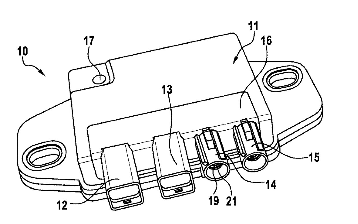
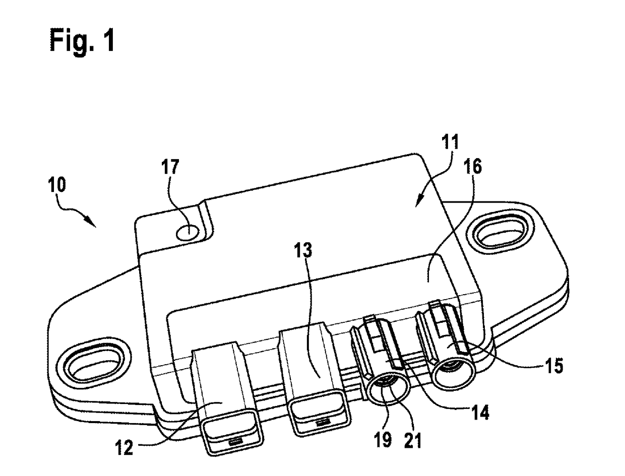
[0025]FIG. 1 illustrates an electronic controller 10 as a component of a driver assistance system, in particular of a navigation system, in a vehicle. The controller 10 is designed to calculate the position of the vehicle or of the controller 10 using satellite-assisted information and additionally using a sensor system, for example for sensing magnetic fields or accelerations or decelerations or pressures.

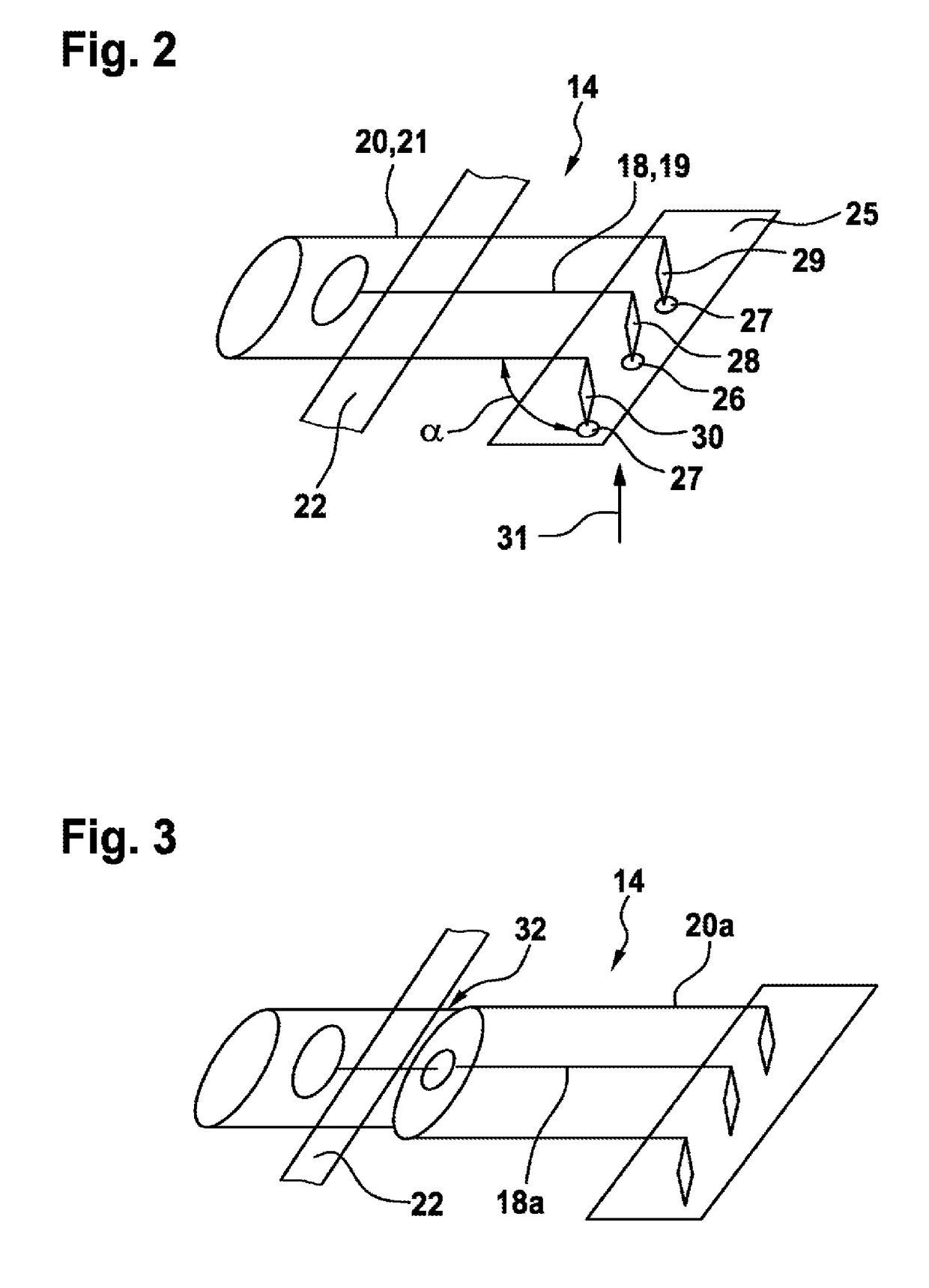
[0026]The housing 11, which is preferably composed of plastic and is manufactured using an injection molding method, of the controller 10 has, for the formation of electrical contact, for example two nano-MQS plug-type connections 12, 13 arranged one next to the other and two high-frequency connections 14, 15, also arranged one next to the other, which are each embodied in the form of a socket on the outside of the housing 11. Of course, the plug-type connections 12, 13 and the high-frequency connections 14, 15 can also have different positions on the housing 11. The two frequency...


PUM


Abstract

The invention relates to an electronic controller (10), having a housing (11), which is preferably made of plastic, having at least one high-frequency connection (14, 15), wherein the high-frequency connection (14, 15) has at least two elements (18; 18a; 18b; 18d, 20; 20a; 20b; 20c; 20d) that form a high-frequency conductor (19), for transmitting a high-frequency signal, and a screening element (21), wherein the two elements (18; 18a; 18b; 18d, 20; 20a; 20b; 20c; 20d) of the high-frequency connection (14, 15) are connectable to a circuit carrier (25) in the interior of the housing (11), and wherein the two elements (18; 18a; 18b; 18d, 20; 20a; 20b; 20c; 20d) of the high-frequency connection (14, 15) are formed on the side facing the circuit carrier (25) in the form of press-in pins (28; 28b; 28d, 29; 29b; 29c; 29d, 51).

Description

BACKGROUND OF THE INVENTION[0001]The invention relates to an electronic controller. In addition, the invention relates to the use of a controller according to the invention.[0002]DE 198 51 455 A1 by the applicant discloses an electronic controller which is a component of a drive unit operated by an electric motor in a motor vehicle, for example a drive unit in the form of a window lifter drive. The known electronic controller is distinguished by the fact that plug connections which are surrounded by a plug connection body are provided for forming electrical contact for components in the interior of the controller. This is done by partially encapsulating the plug connections by means of the material of the plug connection body which as a result forms what is referred to as a pre-mold. The plug connection body which is provided in this respect with the plug connections can either be inserted into a corresponding receptacle of a housing or else connected directly to the housing by enca...

Claims


Application Information

Patent Timeline
Patent Type & Authority Applications(United States)
IPC IPC(8): H01R24/50H01R24/44H01R24/52H01R24/76
CPCH01R24/50H01R24/44H01R24/52H01R24/76H01R2201/02
Inventor HANSEN, JANROJAHN, MARTINLUDWIG, MATTHIASHORTIG, MICHAELSCHRIMPF, THOMASREHM, STEFAN
Owner ROBERT BOSCH GMBH
Learn More