Roadside Delineator Device

Active Publication Date: 2022-08-25
EVANS +1
View PDF12 Cites 0 Cited by
  • Summary
  • Abstract
  • Description
  • Claims
  • Application Information

AI Technical Summary

Benefits of technology

The invention is a delineator that is used on roadsides. It has a breakaway feature that allows the lower part of the delineator to stay in the ground while the upper part can be reused. This saves time and money compared to replacing the entire device.

Problems solved by technology

Sometimes they are used in areas where snow or other inclement conditions may make it difficult for a driver to determine where the side of the road ends and the shoulder of the road begins.
This process takes time and money to fully replace the damaged delineator.

Method used


Image

  • Roadside Delineator Device
  • Roadside Delineator Device
  • Roadside Delineator Device

Examples


Embodiment Construction

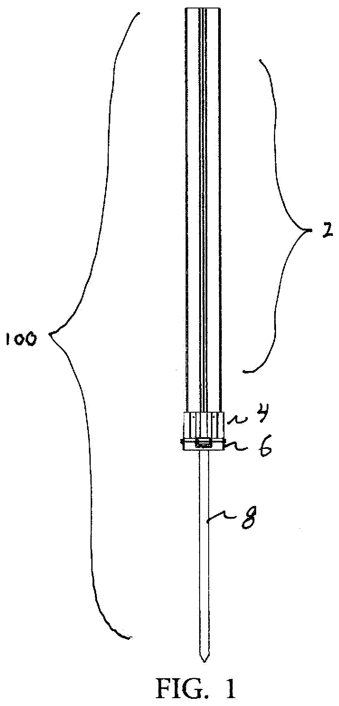
[0023]Referring now to FIG. 1 we see a front view of the entire roadside delineator device of the present invention 100. A lower post 8 is designed to be sunk into the ground. A lower body 6 is attached to the post 8. An upper body 4 is removably attached to the lower body as will be described in detail below. The upper post 2 is usually used to show drivers where the edge of the road is as it meets the shoulder of the road, a bicycle lane part of the roadway, or a pedestrians only part of the roadway. However other uses may be found such as creating a barrier to an item that should be avoided by a vehicle so that the vehicle will not hit the item.

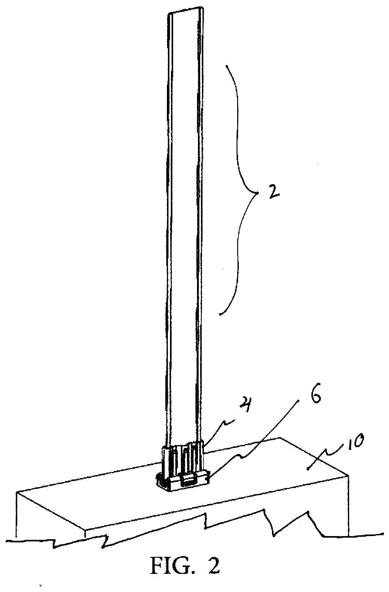
[0024]FIG. 2 is a perspective view of the invention 100 as it is installed into a hard-flat substrate 10 such as packed dirt or concrete.

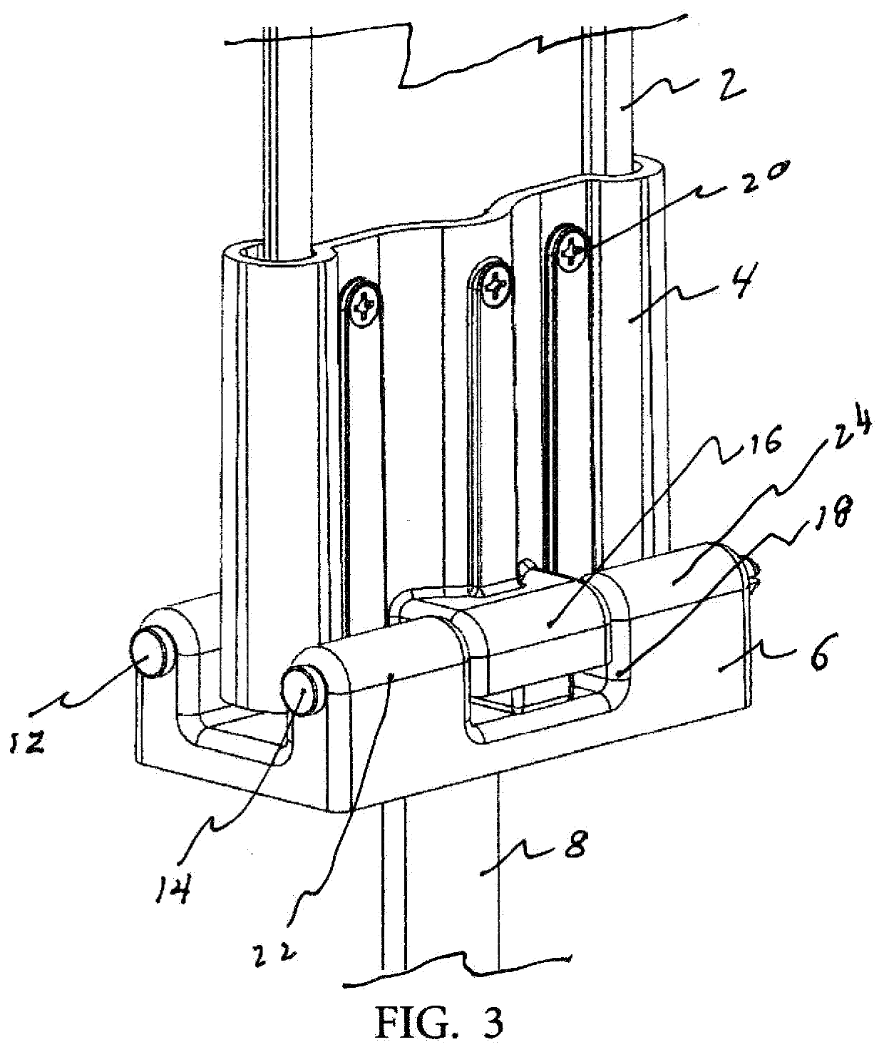
[0025]FIG. 3 is a partial perspective view clearly showing the lower body 6 and its relation to the hollow upper body 4. The upper body is held to the lower body by shear pins 12, 14 as they travel throug...


PUM


Abstract

A roadside delineator device that includes a breakaway shear pin feature that allows the upper portion of the device to break away from the lower portion of the device during a vehicular accident. The upper and lower halves can be reconnected by replacing the broken shear pins. This allows the re-use of components and saves time and money by not having to install a completely new roadside delineator device.

Description

CROSS REFERENCE TO RELATED APPLICATIONS[0001]Not ApplicableSTATEMENT REGARDING FEDERALLY SPONSORED RESEARCH OR DEVELOPMENT[0002]Not ApplicableDESCRIPTION OF ATTACHED APPENDIX[0003]Not ApplicableBACKGROUND OF THE INVENTION[0004]This invention relates generally to the field of roadside delineator devices and more specifically to a roadside delineator that has a breakaway feature.[0005]Roadside delineators are post-like structures used on the side of roads to show drivers where not to drive. Sometimes they are used in areas where snow or other inclement conditions may make it difficult for a driver to determine where the side of the road ends and the shoulder of the road begins. In other cases, they are simply used to alert drivers as to the location of the edge of the road and the beginning of the shoulder next to the road. The current roadside delineators are retained in the ground by a downward facing post and are of a unitary construction so that if a delineator is accidentally hit...

Claims


Application Information

Patent Timeline
IPC IPC(8): E01F9/635E01F9/608
CPCE01F9/635E01F9/61E01F9/608
Inventor EVANSEVANS, LORRI
Owner EVANS
Why Eureka
Try Eureka