Eureka AIR delivers breakthrough ideas for toughest innovation challenges, trusted by R&D personnel around the world.

Cement finishing tool cover

a technology for cement finishing tools and cement walkways, which is applied in the field of cement finishing tool covers, can solve the problems of poor work, poor finish of cement walkways, and often regarded as functional, and achieve the effect of saving money and tim

Active Publication Date: 2017-02-14
FATSCHER EDWARD
View PDF18 Cites 1 Cited by
  • Summary
  • Abstract
  • Description
  • Claims
  • Application Information

AI Technical Summary

Benefits of technology

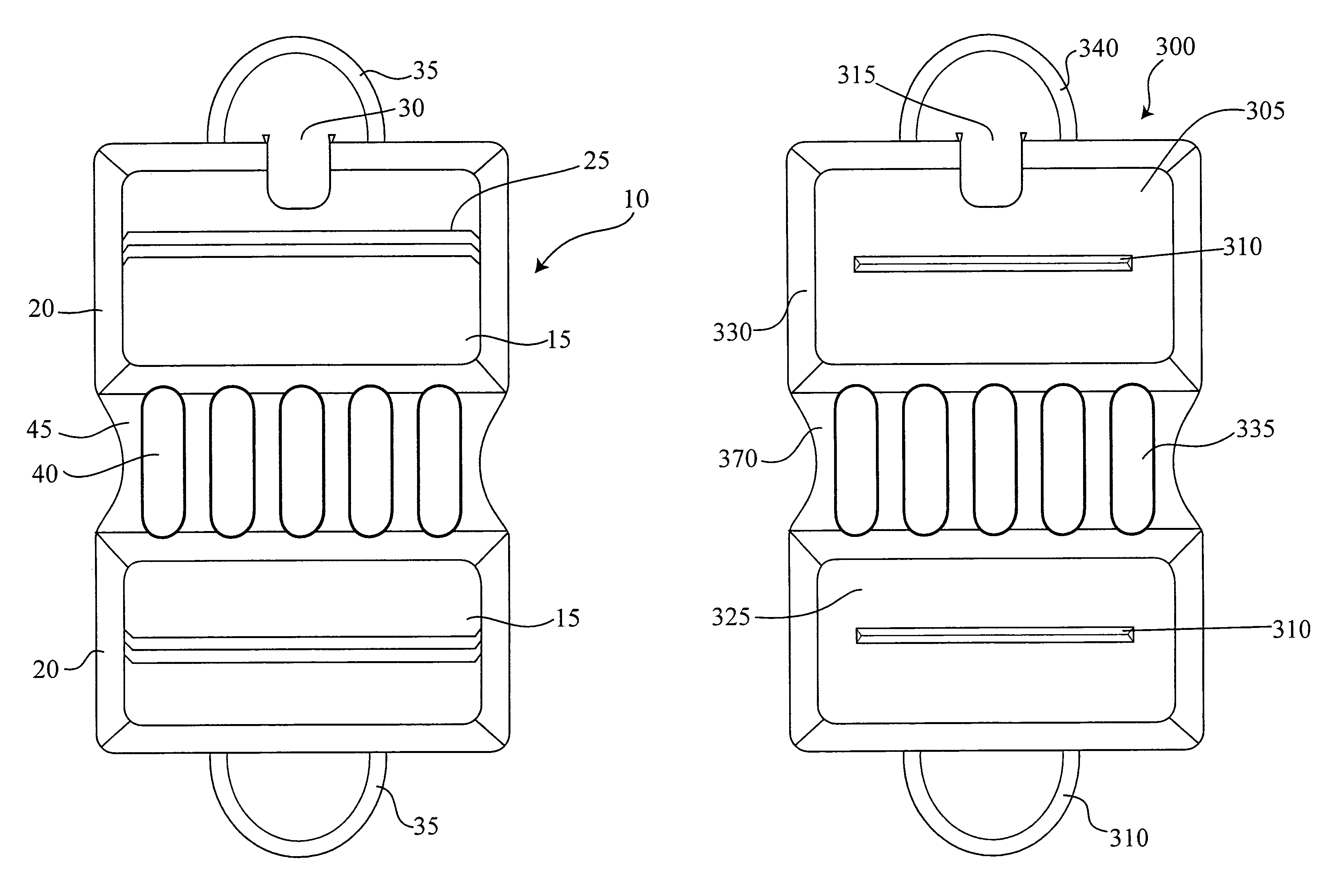
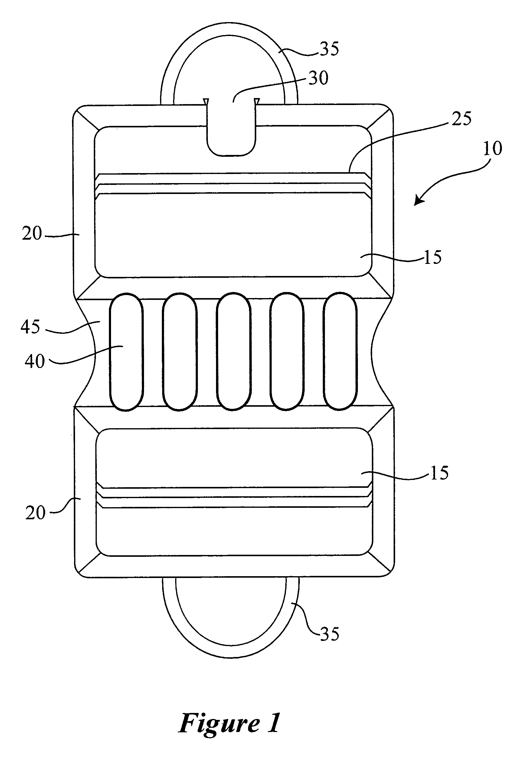
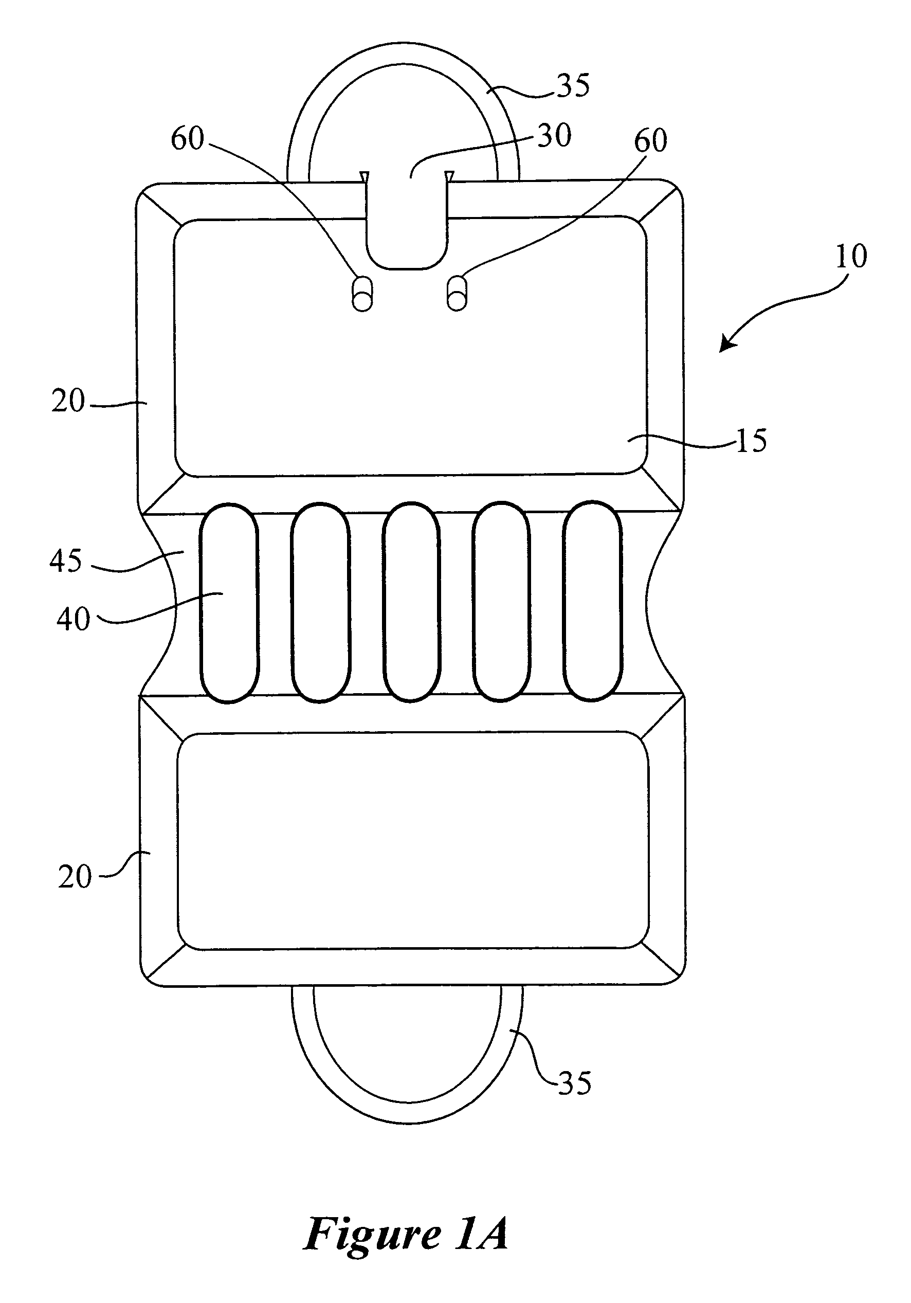
[0008]The present invention is directed to a cement finishing tool cover configured to enclose at least part of a cement finishing tool having a bundle of fibers affixed to a frame at one end thereof. The cement finishing tool cover comprising front and back substantially parallel spaced apart face panels configured to form an enclosure for the cement finishing tool. The front and back face panels having an inside surface and an outside surface wherein at least one of the inside surfaces further comprises a hanging element that is configured to engage at least portion of the frame of the cement finishing tool. Once the frame engages the hanging element, it suspends the cement finishing tool inside the cover and prevents the bundle of fibers from protruding out of a bottom portion. That is, the cover secures and suspends the cement finishing tool inside the enclosure of the cover / case thus preventing the fibers from contacting a surface and becoming damaged. Since it is important that the fibers of the tool remain straight and in good condition in order to provide a quality finish to a cement surface, it is important to protect the fibers from becoming bent when stored. The cover of the present invention achieves just that saving money and time in the cement construction business.
[0009]In one embodiment of the present invention a cement finishing tool cover configured to cover a cement finishing tool having a bundle of fibers affixed to a frame at one end thereof and at least one bore in said frame is provided. This structure resembles the first embodiment summarized above having front and back substantially parallel spaced apart face panels that are configured to form an enclosure for the cement finishing tool. The front and back face panels have an inside surface and an outside surface and at least one of the inside surfaces of the face panels comprises at least one peg-like extension that is configured to mate with at least one bore so as to secure the cement finishing tool to the cover. This prevents the tool when thrown in the back of a truck or tool bag from becoming damaged and thereby saving time and money for the cement technician.

Problems solved by technology

A cement walkway with a poor finish, although functional, is often regarded as poor work by the homeowner or landowner requesting the job.
In addition, when on a job time and money is wasted when the finishing tool is removed from the truck and it has bent / deformed bristles form being thrown in the back of the truck.
If the finishing tool's head were stored on an uneven surface, the sheer weight of the head itself would cause the bristles to become disfigured and most likely stay that way.
This makes the tool unusable for its intended purpose.
That is if the tool is used in this condition the uneven bristles will create marks / lines / uneven tracks in the cement that is considered to be a poor finish.
Often, it is first realized that the finishing tool used to finish the surface of the cement is defective at the end of the job when it is time to use the tool to finish the surface.
This leads to a poor finish and extra work to try to make the surface look as good as possible.
Not to mention adding an addition cost to the job to replace the finishing tool for the next job.
However, since these tools are often stored in a work trucks, even storing the bristled heads with care cannot prevent shifting of tools when in transit which usually cause damage to the bristles and therefore rendering the finishing tool unusable.
Even if the bristles are covered for protection, the finishing tools own weight will damage the bristles in transit.

Method used


Image

  • Cement finishing tool cover
  • Cement finishing tool cover
  • Cement finishing tool cover

Examples


Embodiment Construction

[0020]The present invention may be understood more readily by reference to the following detailed description of the invention taken in connection with the accompanying drawing figures, which form a part of this disclosure and in which like numbers indicate like features. It is to be understood that this invention is not limited to the specific devices, methods, conditions or parameters described and / or shown herein, and that the terminology used herein is for the purpose of describing particular embodiments by way of example only and is not intended to be limiting of the claimed invention.

[0021]Also, as used in the specification and including the appended claims, the singular forms “a,”“an,” and “the” include the plural, and reference to a particular numerical value includes at least that particular value, unless the context clearly dictates otherwise. Ranges may be expressed herein as from “about” or “approximately” one particular value and / or to “about” or “approximately” another...


PUM


Abstract

Cement finishing tool cover is provided that is configured to cover a cement-finishing tool having a bundle of fibers affixed to a frame at one. The case having a pair of spaced opposite substantially parallel face panels having an inside surface and an outside surface. At least one of said inside surface of the pair of spaced opposite substantially parallel face panels is equipped with a hanging element that is designed to engage at least portion of the frame of the cement finishing tool so as to prevent the bundle of fibers from coming in contact with a surface when the case is placed on a surface. This protects the fibers from becoming disfigured and adversely affecting the finishing of a cement surface when used.

Description

CROSS REFERENCE TO RELATED APPLICATIONS[0001]This application claims priority to U.S. provisional application No. 61 / 400,028 filed Jul. 22, 2010, which is herein incorporated in its entirety by referenceFIELD OF THE INVENTION[0002]The present invention relates to a cover for cement finishing tools and more particularly pertains to a cover specifically designed to protect the bristles of a finishing tool used for finishing cement surfaces.BACKGROUND OF THE INVENTION[0003]When completing a cement surface arguably the most important part is the finishing of the surface. A cement walkway with a poor finish, although functional, is often regarded as poor work by the homeowner or landowner requesting the job. One way used by almost all masonry workers is the use of cement finishing tools such as fine bristle brooms that are used to smooth out the surface to provide a clean surface that is pleasing to the customer's eye. In order to get a clean, uniform surface, the finishing tools used mu...

Claims


Application Information

Patent Timeline
Patent Type & Authority Patents(United States)
IPC IPC(8): B65D83/10A45C11/26A45C13/00A45D44/18
CPCA45C13/002
Inventor FATSCHER, EDWARD
Owner FATSCHER EDWARD
Why Eureka
Eureka Blog
Learn More