Tool for working on a surface

a technology for working tools and surfaces, applied in the direction of gear teeth, gear cleaners, gear teeth, etc., can solve the problems of large devices, affecting the work efficiency of workers, and prone to flipping on their elongated sides,

Active Publication Date: 2011-04-19
FULL CIRCLE INT
View PDF82 Cites 6 Cited by
  • Summary
  • Abstract
  • Description
  • Claims
  • Application Information

AI Technical Summary

Benefits of technology

[0003]Another device utilizes a motorized rotating head that rotates rapidly to reduce the number of passes the device must take over an area. These devices are larger and more cumbersome due to the mechanical motor assembly and have a circular, non-continuous “O” shaped working surface due to the need to have access to a bolt. The bolt is seated in the center of the “O” defined by the working surface. This device takes a greater level of skill to master and if used improperly, can damage the surface by dishing to create swirl marks in the surface.

Problems solved by technology

However, when the device is manipulated, due to its narrow configuration, the device tends to flip onto its elongate sides and can damage the surface of a wall, for example, by gouging the surface with the corners or edges of the device, requiring filling or additional sanding to remove the damage.
These devices are larger and more cumbersome due to the mechanical motor assembly and have a circular, non-continuous “O” shaped working surface due to the need to have access to a bolt.
This device takes a greater level of skill to master and if used improperly, can damage the surface by dishing to create swirl marks in the surface.
Further, devices have been proposed to vacuum away dust from the working surface, however, in devices proposed, the air is circulated around the working material (e.g., sand paper) and, therefore, only vacuums the dust that is at the edges of the device.
Such devices have also typically been heavy and, therefore, difficult to maintain in position on the working surface, such as a wall or ceiling, among other surfaces.

Method used


Image

  • Tool for working on a surface
  • Tool for working on a surface
  • Tool for working on a surface

Examples


Embodiment Construction

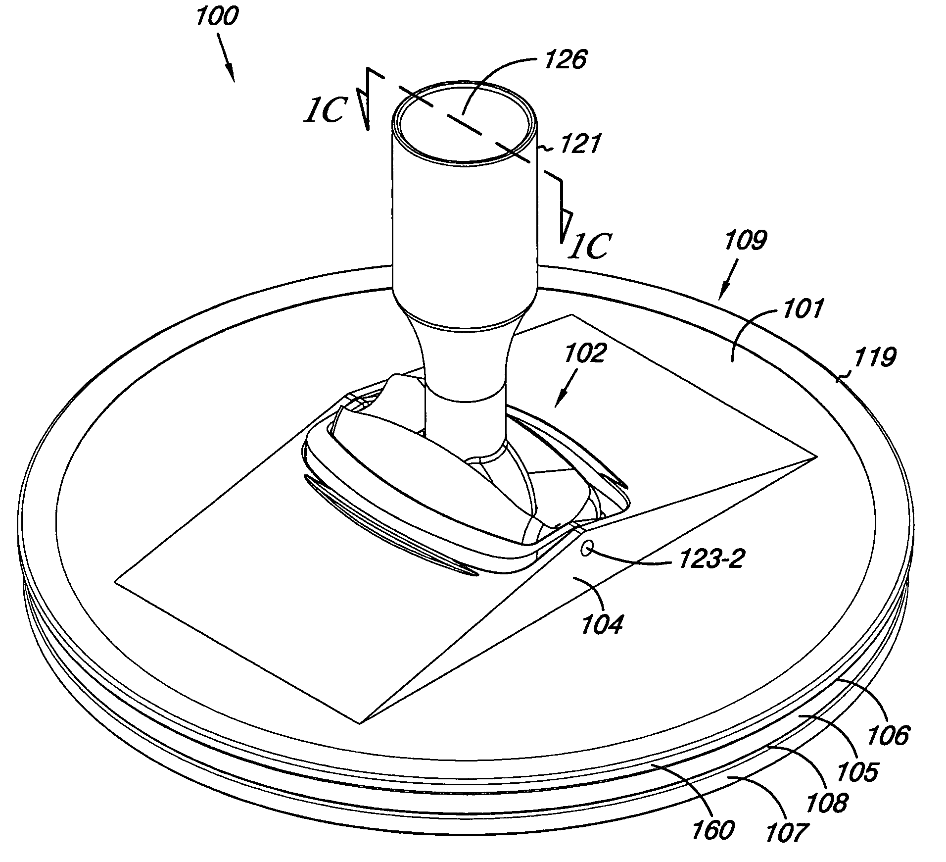
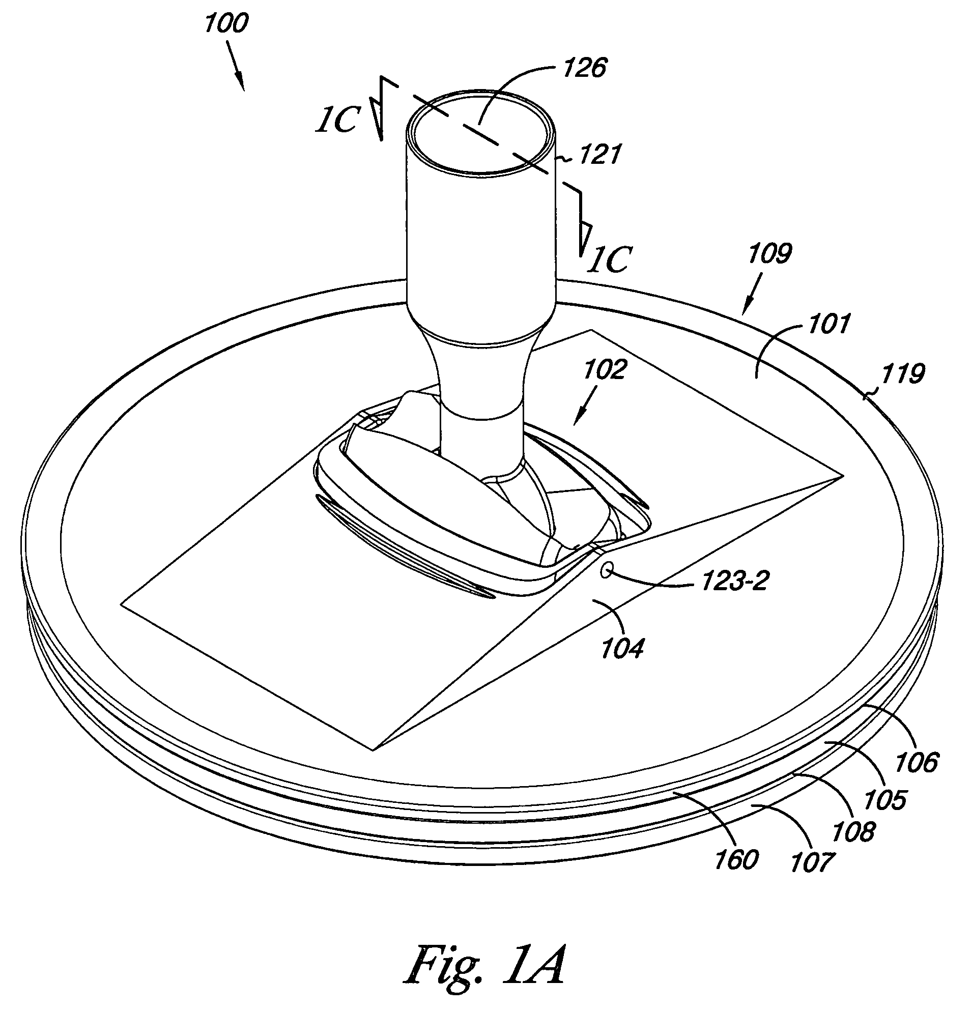
[0022]Embodiments of the present disclosure provide working tools that provide suction to a working surface and / or dust removal from a working surface. For example, one embodiment of a tool includes a tool support having an upper surface and a sidewall defining a cavity defined by the sidewall and the upper surface. The tool includes a base attached to the upper surface of the tool support and a vacuum attachment structure attached to the base. The attachment structure includes a connector member having an opening in a first end for releasable attachment to a vacuum source.

[0023]Some embodiments of a tool according to the present disclosure include a tool support having an upper surface and a sidewall that defines a cavity between the sidewall and the upper surface. Various embodiments include an attachment structure attached to the tool support. The attachment structure can include a connector member having an opening in a first end for releasable attachment to a handle and / or vacu...


PUM


Abstract

Embodiments of the present disclosure provide working tools that provide suction to a working surface and / or dust removal from a working surface. One embodiment of a tool includes a tool support having an upper surface and a sidewall defining a cavity defined by the sidewall and the upper surface. The tool includes a base attached to the upper surface of the tool support and a vacuum attachment structure attached to the base. The attachment structure includes a connector member having an opening in a first end for releasable attachment to a vacuum source.

Description

INTRODUCTION[0001]Hand held tool devices have been utilized in many fields for working the surface of a material, such as sanding, polishing, and painting, among others. For example, when fabricating a structure, such as a wall or ceiling in a building, oftentimes it is necessary to utilize a sanding device to smooth the surface of the structure. In response to this need, in the field of sanding devices, for example, various devices have been proposed.[0002]One device utilizes a sanding head having an elongate rectangular shape. Such heads are designed to accommodate a standard sized elongate sheet of sand paper, thereby making the supply of sanding paper readily accessible. However, when the device is manipulated, due to its narrow configuration, the device tends to flip onto its elongate sides and can damage the surface of a wall, for example, by gouging the surface with the corners or edges of the device, requiring filling or additional sanding to remove the damage.[0003]Another ...

Claims


Application Information

Patent Timeline
Patent Type & Authority Patents(United States)
IPC IPC(8): B24D15/00
CPCB24B7/184B24D15/00B24B55/10
Inventor ANNIS, KENT V.
Owner FULL CIRCLE INT
Why Eureka
Try Eureka