Non-Rotating T-Nut and Screw Catch for Use in a Chair Panel and Method for Using the Same

a technology of screw catches and t-nuts, which is applied in the direction of screws, threaded fasteners, furniture parts, etc., can solve the problems of high torque pressure on the plastic t-nut, delay and additional expense, and achieve the effect of eliminating a manufacturing step, reducing materials, and saving time and money

Active Publication Date: 2019-11-21
DANIEL PAUL CHAIRS
View PDF0 Cites 0 Cited by
  • Summary
  • Abstract
  • Description
  • Claims
  • Application Information

AI Technical Summary

Benefits of technology

[0005]In order to prevent the traditional T-nut, such as is typically utilized in the manufacture of the upholstered panels of a metal frame chair, from spinning while a screw is driven into it, the present invention provides an oval-shaped T-nut that is received within an oval receiver machined into the upholstered first seat back panel, referred to herein as the inside panel, which is secured to a chair frame. Further, this eliminates the necessity of stapling the traditional plastic T-nut to the chair panel, thus reducing materials and eliminating a manufacturing step, thus saving time and money associated with the manufacture of an upholstered metal frame chair.
[0006]In addition to the oval-shaped T-nut described herein, a novel U-shaped screw catch is also provided. The U-shaped screw catch is received within an oval receiver machined into one of the upholstered panels, preferably the inside panel, the and is adapted to receive and engage the corresponding barbs or threads on a nylon or plastic push rivet which projects from the other upholstered chair panel. The combination of the push rivet and the U-shaped screw catch serve to secure the upholstered chair panels to one another.

Problems solved by technology

This action creates high torque pressure on the plastic T-nut.
This may then require the chair component to be disassembled and repaired, which results in delay and additional expense.

Method used


Image

  • Non-Rotating T-Nut and Screw Catch for Use in a Chair Panel and Method for Using the Same
  • Non-Rotating T-Nut and Screw Catch for Use in a Chair Panel and Method for Using the Same
  • Non-Rotating T-Nut and Screw Catch for Use in a Chair Panel and Method for Using the Same

Examples


Embodiment Construction

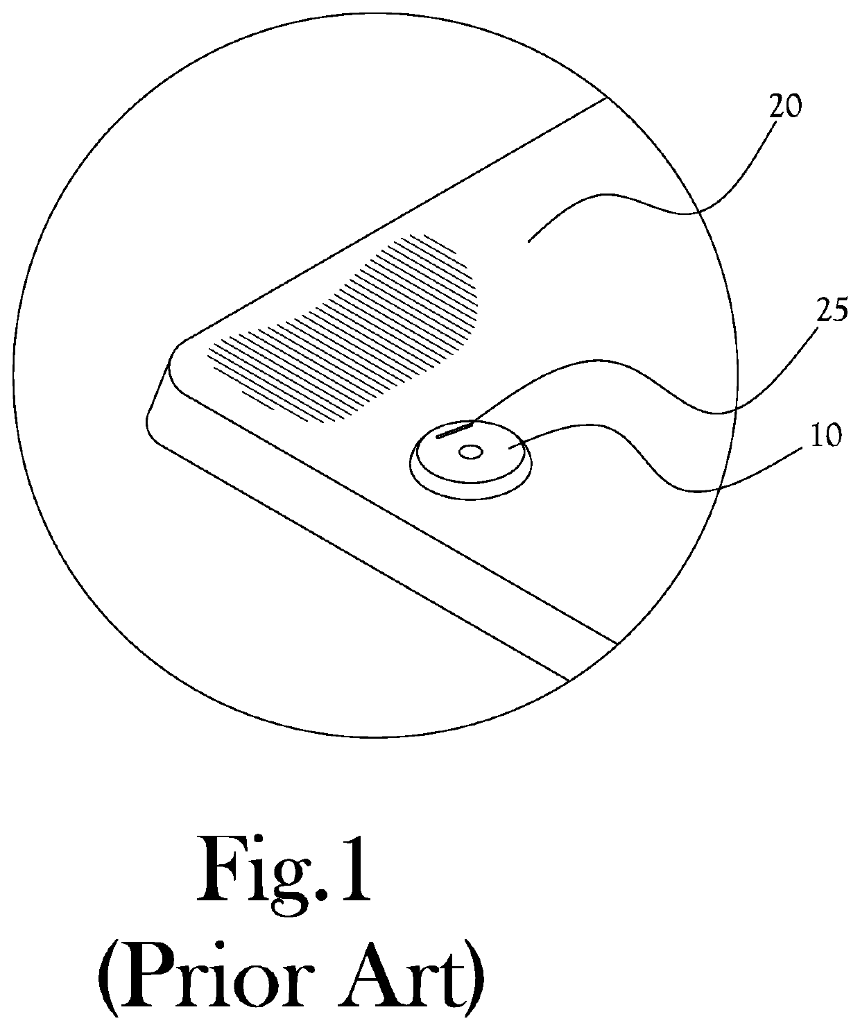
[0018]FIG. 1 illustrates a traditional prior art T-nut 10 utilized in the manufacture of the upholstered seat back panels of a frame chair 15, especially a metal frame chair. While such upholstered panels are found in both the vertical seat back portion and the horizontal seat support section portion of metal frame chair 15, the present description makes specific reference to the inside seat back panel 20 and the outside seat back panel 30 that make up the upholstered back portion of metal frame chair 15 illustrated in FIG. 5. Plastic T-nuts, such as traditional T-nut 10, in this field are typically used with a sheet metal type screw 35. The screw 35 cuts its own treads into the plastic material as the screw 35 is driven into traditional T-nut 10 by powered screw drivers. This action creates high torque pressure on the plastic T-nut 10. In order to prevent the plastic T-nut 10 from spinning as the screw 35 is driven, the plastic T-nut 10 is typically stapled with staple 25 to the in...


PUM


Abstract

An oval-shaped T-nut that is received within an oval receiver machined into the upholstered panel to be secured to a chair frame is provided. The oval shape of the T-nut prevents the oval-shaped T-nut from rotating when a screw is driven into the T-nut. Further, this eliminates the necessity of stapling the traditional plastic T-nut to the chair panel, thus saving time and money associated with the manufacture of an upholstered metal frame chair. In addition to the oval-shaped T-nut described herein, a novel U-shaped screw catch is also provided which cooperates with a barbed nylon or plastic push rivet to secure the upholstered chair panels to one another. Further, a method for connecting upholstered seat back panels to the tabs positioned on the back frame of a chair, utilizing the T-nut and the screw catch is disclosed.

Description

CROSS-REFERENCE TO RELATED APPLICATIONS[0001]This application claims the benefit of U.S. patent application Ser. No. 15 / 478,527, filed on Apr. 4, 2017, which is incorporated herein in its entirety by reference.STATEMENT REGARDING FEDERALLY SPONSORED RESEARCH OR DEVELOPMENT[0002]Not ApplicableBACKGROUND OF THE INVENTION1. Field of Invention[0003]The invention relates to an improved T-nut, a U-shaped screw catch for use in securing two upholstered chair panels to one another, and a method for using the same. More particularly, it relates to an oval-shaped T-nut which is tightly received in an oval-shaped receiver, for preventing the T-nut from rotating within the chair panel as a screw is threadably received by the T-nut. The U-shaped screw catch is adapted to receive a nylon or plastic barbed push rivet.2. Description of the Related Art[0004]In the field of chair manufacturing, especially metal frame chair manufacturing, it is known to have upholstered chair panels, particularly with...

Claims


Application Information

Patent Timeline
Patent Type & Authority Applications(United States)
IPC IPC(8): F16B19/10F16B13/00F16B12/30
CPCF16B5/065F16B12/30F16B9/052F16B21/073A47B2230/0037F16B13/001F16B19/1081F16B5/0225F16B37/0878
Inventor BARILE, PETER W.HELM, TODD EDWARD
Owner DANIEL PAUL CHAIRS
Why Eureka
Try Eureka