
Electronic percussion instrument and sound production control method thereof

Active Publication Date: 2022-10-06
ROLAND CORP
View PDF32 Cites 1 Cited by
  • Summary
  • Abstract
  • Description
  • Claims
  • Application Information

AI Technical Summary

Benefits of technology

This patent describes a method for controlling the sound of an electronic percussion instrument by detecting when it is being hit and adjusting the sound to match that hit. This is done by using an electrostatic capacitance sensor that detects changes in capacitance caused by user touch. The method can provide a more immersive experience for the player and enable more precise control over the sound of the instrument.

Problems solved by technology

Therefore, it is not possible to perform choke control.
In addition, it is not possible to realize playing such as touching the struck surface and muting as with an acoustic cymbal or the like.
However, in this electronic percussion instrument device, even if it can be detected whether a touch has occurred, it is difficult to detect a state (degree) of touching.

Method used


Image

  • Electronic percussion instrument and sound production control method thereof
  • Electronic percussion instrument and sound production control method thereof
  • Electronic percussion instrument and sound production control method thereof

Examples


first embodiment

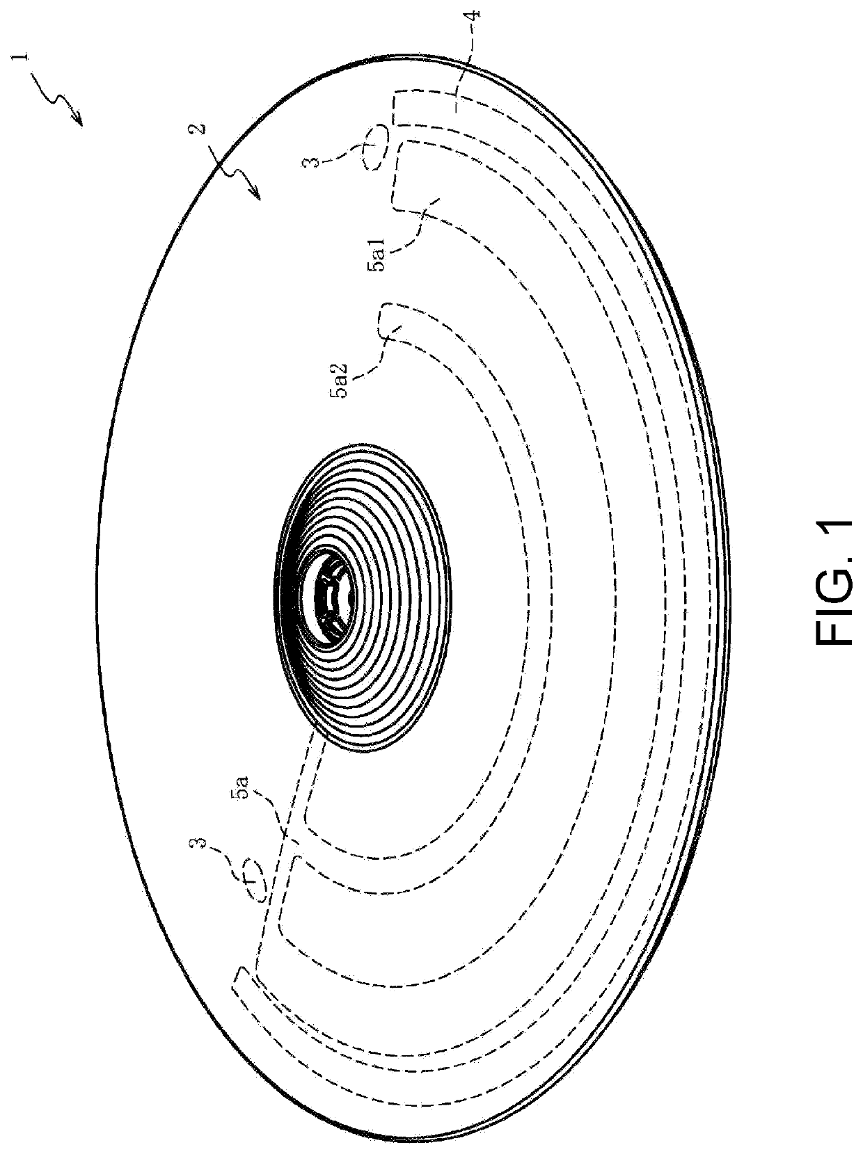
[0027]Preferable embodiments of the present invention will be described below with reference to the appended drawings. the present invention will be described with reference to FIG. 1 to FIGS. 5(a) and 5(b). First, a schematic configuration of an electronic cymbal 1 as an electronic percussion instrument of the present invention will be described with reference to FIG. 1. FIG. 1 is a perspective view of the electronic cymbal 1 according to an embodiment of the present invention.

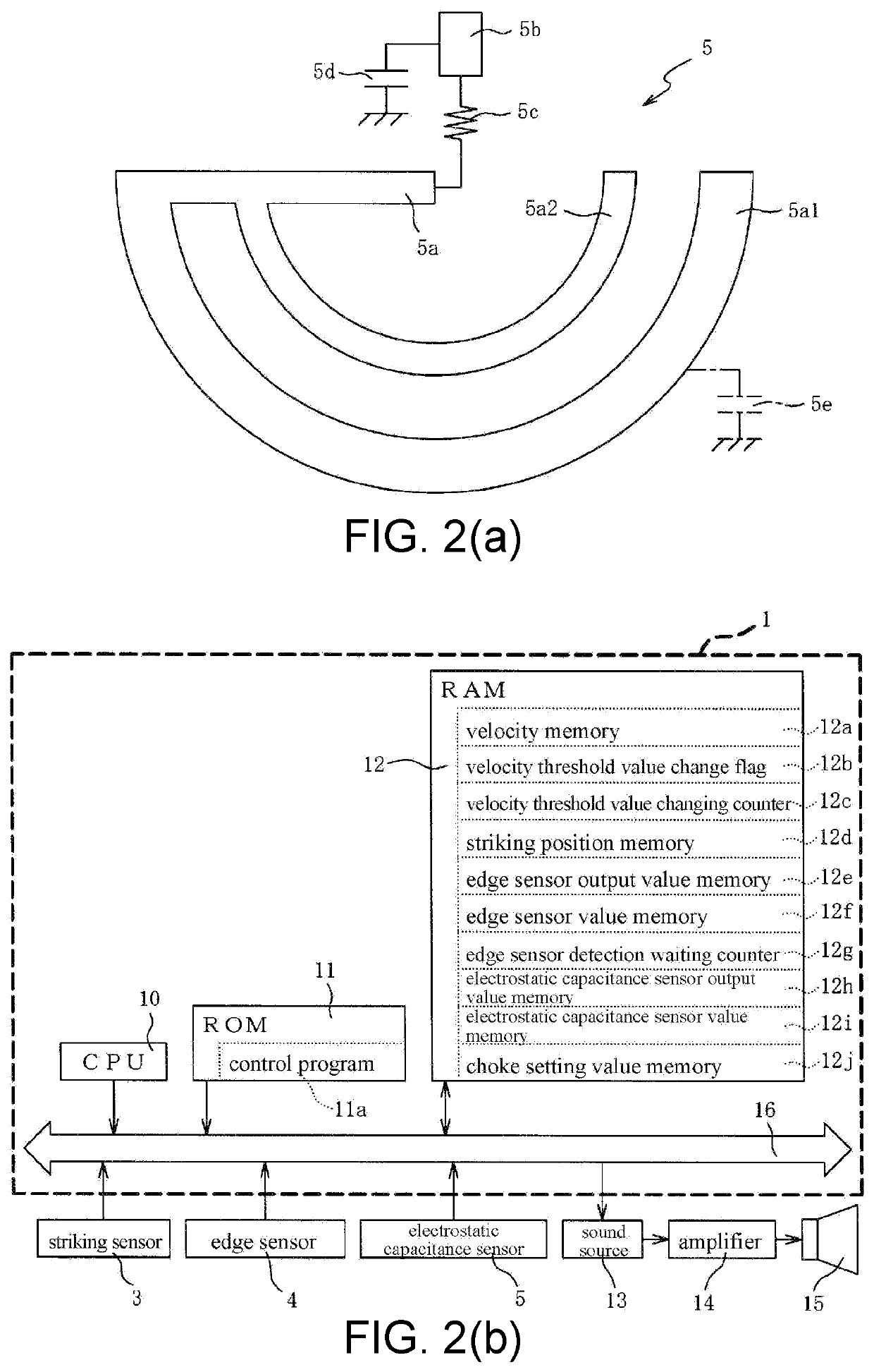
[0028]The electronic cymbal 1 includes a struck surface 2, a striking sensor 3, an edge sensor 4, and an electrostatic capacitance sensor 5. The struck surface 2 is formed of a disk-shaped rubber member which is struck by a user with a stick, and is formed to cover a disk-shaped plate (not shown) disposed on the side opposite to the struck surface 2.

[0029]The striking sensor 3 is a piezoelectric sensor configured to detect striking on the struck surface 2, and is disposed at two places on the disk-shaped plat...

second embodiment

[0084]FIG. 7 is a block diagram showing an electrical configuration of an electronic cymbal 100 of the The electronic cymbal 100 includes the CPU 10, the ROM 11, the RAM 12, the striking sensor 3, the edge sensor 4, the electrostatic capacitance sensor 5, the second electrostatic capacitance sensor 6, and the sound source 13, and these are connected to one another via the bus line 16. The amplifier 14 is connected to the sound source 13, and the speaker 15 is connected to the amplifier 14.

[0085]The RAM 12 is a memory in which various types of work data, flags and the like used when the CPU 10 executes a program such as the control program 11a are stored in a rewritable manner. In the RAM 12, the velocity memory 12a, the velocity threshold value change flag 12b, the velocity threshold value changing counter 12c, the striking position memory 12d, the edge sensor output value memory 12e, the edge sensor value memory 12f, the edge sensor detection waiting counter 12g, the electrostatic...


PUM


Abstract

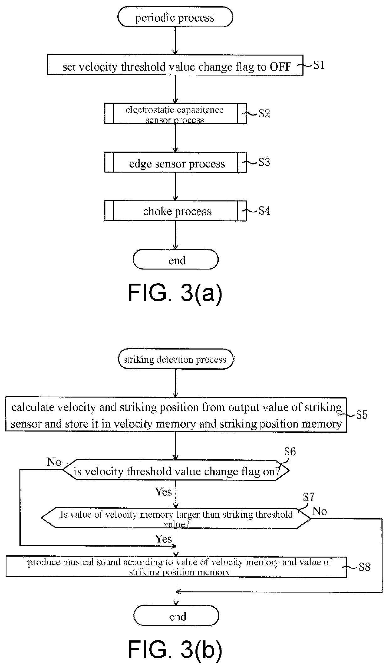
An electronic percussion instrument and sound production control method thereof are provided. In an electronic cymbal, the output of a musical sound is controlled in accordance with the results of detection from a strike sensor when the strike sensor detects a strike on a striking surface. While the musical sound is output, if a user touches the striking surface, an electrostatic capacitance sensor outputs an output value in accordance with the contact condition so that the musical sound is attenuated in accordance with the output value while being output. Therefore, the user can attenuate the musical sound being output in accordance with the contact conditions on the striking surface, thereby silencing the musical sound by way of the action similar to that of the acoustic cymbal choke that is the action of touching the striking surface.

Description

CROSS-REFERENCE TO RELATED APPLICATION[0001]The present application is a continuation application of U.S. application Ser. No. 16 / 330,372 filed on Mar. 5, 2019, now allowed. U.S. application Ser. No. 16 / 330,372 is a 371 application of the International PCT application Ser. No. PCT / JP2017 / 028803, filed on Aug. 8, 2017, which claims the priority benefits of Japan Patent Application No. 2016-172801, filed on Sep. 5, 2016. The entirety of each of the above-mentioned patent applications is hereby incorporated by reference herein and made a part of this specification.TECHNICAL FIELD[0002]The present invention relates to an electronic percussion instrument. Particularly, the present invention relates to an electronic percussion instrument that can realize an operation similar to choke playing in an acoustic percussion instrument.DESCRIPTION OF RELATED ART[0003]An electronic cymbal is one type of electronic percussion instrument. In an electronic cymbal in Patent Literature 1, a band-like p...

Claims


Application Information

Patent Timeline
IPC IPC(8): G10H3/14G10H1/34G10H3/10
CPCG10H3/146G10H1/34G10H3/10G10H1/0551G10H2230/321G10H2220/525
Inventor TAKASAKI, RYOMORI, YOSHIAKIMORITA, KENJIYOSHIKUNI, NORIHIRO
Owner ROLAND CORP
Learn More